SCREW COMPRESSORS SPECIALIST | Customer Satisfaction Is Our Goal | SCS is a WORLDWIDE leader of Screw Compressors
* In Shop Overhaul *Machine Shop In House *Cast Iron Housing Repair *Balancing *Industrial Hard Chrome Rotor and Seal Journal *Industrial Hard Chrome Piston Rod *Laser Alignment *Fast Turn Around Time *OEM Parts *Fast Respond *OEM Paint or Customer Specification *Emergency 24-7 Service *New Compressors *Preventive Maintenance Vibration Analysis Oil Analysis *Remanufactured Compressors *Exchange Program
MYCOM C Series Compressor Service, Parts and Overhaul
Model: C Series Compressor

About MYCOM:
Mayekawa has been deeply committed to the refrigeration industry for more than 80 years. During this time Mayekawa has developed high quality, easy to handle and cost-effective thermal technology. Mayekawa offers a comprehensive range of compressors with hundreds of models developed in response to the variety of applications required in refrigeration. New gas compressors have been developed for the specific needs of gas compression systems based on our experience in applications including helium, hydrogen, water vapor, chlorine, hydrogen chloride, and hydrogen sulfide( not including oxygen and acetylene). Mayekawa never cease building on MYCOM experience with research and development to constantly improve their compressor products.

Screw Compressors Service Parts and Repair
FREE SCREW COMPRESSOR INSPECTION
Let us determine the extent of your problem, give you a full report, and best plan of action to get your compressor up and running as soon as possible. SCS does offer 24/7 around the clock repairs to eliminate your downtime. In some case you could be eligible for SCS exchange program offering a very quick turnaround. Screw Compressors Service offers free screw compressor inspections for the following brands:
Trusted Compressor Overhaul and Rebuild Company. Screw Compressor Repair has been in the Industrial Industry for more than 30 years.
IN SHOP OVERHAUL
SCS shop is equipped with all necessary tools and equipments - crane, forklift, special tool, etc. SCS tear down table has a building oil rail drain to catch all oil drain from compressor during disassembly so there is no oil on the floor that may cause slip and fall. PPE is always available for everyone. Safety training are done year round – safety certifications is required to work in the job site.
Hotshot Pickup & Delivery Services
24/7 Nationwide Hotshot Delivery Service to and from the location of the compressor needing repair.


Chapter 1 Safety
1.1 Strict Requirements and Prohibitions
1.1.1 Strict Requirements (Do’s)
1.1.1.1 Do’s on Operation
Make sure to install safety and protective devices on the package unit.
Regularly inspect the safety and protective devices if they function properly.
If the safety or protective devices do not work properly or if this product operates abnormally, immediately stop the operation and report to your supervisor. Obtain his/her approval and direction before restarting the compressor.
If this product stops for unknown reasons, immediately inform your supervisor of it. Obtain his/her approval before restarting this product.
Some types of refrigerants emit bad smell or toxic gases when they leak. Make sure to ventilate the air during operation.
For the properties of refrigerant and lubricating oil (corrosiveness, decomposability or toxicity), be sure to obtain the Safety Data Sheet (SDS) and follow the relevant information.
When stopping the operation of this product, close the suction and discharge side shut-off valves and turn "OFF" the motor (main power), heater power, and control power.
1.1.1.2 Do’s on Maintenance
Prepare work procedures based on a work schedule. Be sure to perform danger forecasting before starting the work.
Before performing the work together with at least one other person, thoroughly confirm each other's work details and procedures to acknowledge the other worker's movement.
When troubleshooting during operation or before performing setup, cleaning, maintenance or inspection of this product, always turn OFF the main power to the motor and control power and
other devices. Also, lock and tag out them to prevent the power from being supplied erroneously during operation.
When troubleshooting during operation or before performing setup, cleaning, maintenance or inspection of this product, confirm that the pressure inside this product and the package unit is
at atmospheric pressure.
Some refrigerants in use generate bad smell or toxic gases, or may cause deficiency of oxygen. Before starting work, measure oxygen concentration in the work area as necessary. Ventilate the area well. Be sure to keep the area well ventilated until the work is finished.
For the properties of refrigerant and lubricating oil (corrosiveness, decomposability or toxicity), be sure to obtain the Safety Data Sheet (SDS) and follow the relevant information.
After using tools always restore to designated place and never leave tools in the package unit. 1.1.1.3 Do’s on Lockout/Tagout after Shutting Off the Power
Attach lockout/tagout mechanism to the main breakers of motor main power and control power. Lockout/tagout after power off is a very effective means to secure safety. It can prevent the power source from being turned on by accident by two or more workers which may cause injury to other worker(s).
If there are any possibilities of danger during works (especially during cleaning, maintenance and inspection, and troubleshooting), turn "OFF" the motor main power and control power, and
perform lockout/tagout.
In the following situations, workers may neglect to perform power source shutoff or lockout/tagout. Clearly notify the workers of the necessity of lockout/tagout.
It is assumed that workers do not perform lockout/tagout before starting work because it is troublesome, and only turn "OFF" the main motor and control power.
It is assumed that workers only turn off the main motor and control power and do not lockout/tagout the main motor and control power, because they judge that there is no danger.
1.1.1.4 Do’s about Personal Protective Gear
Prepare and use protective gear complying with the safety standards of the regulations.
Check the function of each protective gear before using.
Wear designated clothes such as work outfits, with their cuffs tightly closed.
Do not wear any neckties or jewelry as there is a risk of being entangled by a movable part or rotating part. Put on a helmet as your hair may get entangled.
Do not have anything in your pocket to prevent objects from falling into the package unit.
1.1.1.5 Do’s about Handling of Hazardous and Toxic Substances
Obtain the Safety Data Sheet (SDS) from manufacturers of hazardous and toxic substances. Check the SDS and follow the handling instructions recommended by the manufacturers to handle and store those substances.
1.1.1.6 Do’s about Handling Emergency Situations
Formulate an emergency action plan complying with the regulations, and post it on a safe place.
1.1.1.7 Do’s about Waste Oil, Fluid, and Materials
Disposing of refrigerant and oil used for this product are subject to a number of regulations for the environmental protection purposes. Follow the local, state, federal acts and regulations
and your company's rules when disposing of such waste oil, fluid and materials.
1.1.1.8 Other Do’s
Clean the floor around the entire package unit. Provide a safety passage.
Walk only on the areas set up as a work floor. Also, do not leave tools and cleaning solutions in that area.
If water or oil is spilled on this product or the floor, immediately wipe it off to prevent workers from slipping and getting injured.
1.1.2 Prohibitions (Don’ts)
Do not remove or relocate any safety device, including electrical interfaces.
Do not disable any safety device by short-circuiting or bypassing without any permission.
Do not leave this product unsafe and unattended, by removing a safety cover or some other measures.
Do not touch, clean or lubricate any part of this product which is moving.
Do not touch relays or electric systems such as terminal block with bare hands when turning on the power.
1.2 Warnings
The warning messages described in this manual warn dangerous situations that may arise during work by using the following four categories. Neglecting such warnings may cause accidents, resulting in personal injury or even death. Also, this product or its auxiliary equipment may be heavily damaged. Therefore, be sure to always observe the instructions of the warnings.
1.3 Residual Risks
The following information assumes that this product is operated or inspected/maintained while being used in general refrigerating/cold storage/gas compression package units. Note that all hazardous sources cannot be predicted for the applications mentioned. Devise appropriate countermeasures for hazardous sources in your systems.
Table 1-2 Hazardous Sources
Hazardous sources : Predicted hazard : Countermeasures in operation : Countermeasures in cleaning, inspecting, and replacing parts
A Motor and compressor coupling
Refer to Figure 1-1
Caught in due to contact Install coupling cover and prohibit opening.
Keep away.
Turn off motor main power and control power, and conduct lockout/tagout.
B Motor terminals Electric shock caused by contact with live wires or electrical leakage
Keep away.
Do not open terminal boxes.
Do not touch terminal boxes.
Turn off motor main power and control power, and conduct lockout/tagout.
C Compressor low-stage side suction casing
Refer to Figure 1-1
Frostbite due to contact
Contact with or inhalation of hazardous substances generated by leakage of refrigerant or the like
Keep away and do not touch.
Wear protective gear.
Detect gas leakage.
Wear protective gear.
Work under room temperature.
D Compressor intermediate piping (low-stage discharge port to high stage suction port)
Refer to Figure 1-1
Burn injury due to contact
Contact with or inhalation of hazardous substances generated by leakage or spout of refrigerant or the like
Keep away and do not touch
Wear protective gear
Gas leakage detection
Wear protective gear
Work in temperatures below 40 °C
E Compressor high-stage side discharge casing and discharge piping
Refer to Figure 1-1
Burn injury due to contact
Contact with or inhalation of hazardous substances generated by leakage or spout of refrigerant or the like
Keep away and do not touch.
Wear protective gear.
Detect gas leakage.
Wear protective gear.
Work at a temperature of not higher than 40°C.
F Check valves/service valves and joints on each section of the package unit
Contact with or inhalation of hazardous substances generated by mishandling or leakage
Frostbite or burn due to contact
Sufficient ventilation
Indicate valve open/close state.
Keep away and do not touch.
Wear protective gear.
Sufficient ventilation
Wear protective gear.
Tagout for controlled valve
G Solenoid valves/ electric valves on each section of the package unit
Electric shock caused by contact with live wires or electrical leakage
Pinched due to contact with driving part
Install protective cover on terminals, and prohibit opening.
Keep away and do not touch.
Wear protective gear.
Turn off each breaker and the control power, and conduct lockout/tagout.
Wear protective gear.
H Electric components in each section of the package unit (oil heater, protective switch, etc.)
Electric shock caused by contact with live wires or electrical leakage
Pinched due to contact with driving part
Install protective cover on terminals, and prohibit opening.
Keep away and do not touch.
Wear protective gear.
Turn off each breaker and the control power, and conduct lockout/tagout.
Wear protective gear.
I Package unit oil drains
Contact with hazardous substances generated by leakage or spout
Burn caused by contact with high-temperature fluid
Sufficient ventilation
Keep away and do not touch.
Wear protective gear.
Sufficient ventilation
Wear protective gear.
Work at a temperature of not higher than 40°C.
J Noises Damage caused by noise Wear protective gear. —

1.4 Safety Devices
For safe use and protection of this product, make sure to attach safety devices to this product in accordance with the regulations and the following instructions. Safety devices cannot be kept in normal condition unless inspected and maintained at regular intervals. Their maintenance and inspection need to be performed as an important part of the maintenance/inspection work project. Provide users of this product with necessary information on the safety devices, for example, types of the safety devices, installation position, function, and inspection method of safety related devices.
1.4.1 Emergency Stop Button
Overview/Function/Purpose The emergency stop buttons are used to stop this product operation immediately if an emergency occurs in this product.
Installation Positions On the local control panel and in the operation control room
Stop/Restoration Methods The operating procedures for the emergency stop button, i.e., how to stop the operation and restore the normal operating condition, must be clearly defined and the information provided to the user of this product.
Inspection Method/Cycle The emergency stop buttons must be tested before commissioning and must also be periodically re-tested after that. The inspection procedures and the inspection interval for the emergency stop button must be clearly defined and the information provided to the user of this product.
1.4.2 Breakers of Motor Main Power and Control Power (with Lockout/Tagout Mechanism)
Overview/Function/Purpose Turn off the main motor and control power, and if there is any possibility of danger during work (especially during cleaning, maintenance, inspection, or troubleshooting), lockout/tagout devices must be used on the breakers of the main motor and control powers to prevent injuries to workers in case the power is turned on accidentally during work.
Methods of Performing and Releasing Lockout/Tagout Make sure to clearly notify methods of performing and releasing lockout/tagout referring to the regulations created by Occupational Safety & Health Administration (OSHA) or local governing body.
Inspection Method/Cycle The inspection procedures and the inspection interval for the lockout/tagout devices, must be clearly defined and the information provided to the user of this product.
1.4.3 Compressor Protective Devices
Be sure to adjust the set values and check operation of the protective devices at the commissioning.
Overview/Function/Purpose These protective devices are used to protect this product.
Protecting from discharge temperature rise (DT) This device activates and stops the compressor operation when the compressor discharge temperature gets equal to or higher than the set value. Install a temperature sensing port to the discharge pipe.
Protecting from oil temperature rise (OT) This device activates and stops the compressor operation when the compressor oil temperature gets equal to or higher than the set value. Install a temperature sensing port to the oil supply pipe of the package unit (after the oil cooler).
Protecting from high pressure (HP) This device activates and stops the compressor operation when the compressor discharge pressure gets abnormally high due to mishandling of the compressor or suspension of water supply to the condenser. This device prevents explosion of the equipment and components. Install a pressure sensing port to the discharge pipe.
Protecting from intermediate pressure (IP) This device activates when the intermediate pressure of the compressor gets equal to or higher than the set value and properly controls the compressor. In some cases, this device stops the compressor operation. Install a pressure output port to the package unit's intermediate gas pipe (or compressor's intermediate gas pressure output port).
Protecting from suction pressure drop (LP) This device activates and stops the compressor operation when the compressor suction pressure gets equal to or lower than the set value. Install a pressure sensing port to the suction pipe.
Protecting from oil pressure (OP) This device activates and stops the compressor operation when the differential pressure to supply oil to the compressor (= lubrication oil supply pipe pressure − compressor discharge pressure) gets equal to or lower than the set value, due to insufficient lubricant, clogged filter or mixture of refrigerant into the lubrication oil. This device prevents the sliding portion from being abnormally worn or seized. Install a pressure sensing port to the package unit's oil supply pump (after the oil pump) and the discharge pipe.
Protecting from motor over-current (OCR) This device activates and applies appropriate control when the current gets equal to or higher than the set level flows. In some cases, this device stops the compressor operation. This device is normally installed inside the control panel.
Connection Positions and Settings Specify the connection position and setting for each compressor protective device, and make sure to provide users of this product with them.
Make sure that the set values do not exceed the operating limits shown in Section 2.3.2 and Table 2-2 in this manual Chapter 2.
Inspection Method/Cycle Compressor protective devices require operation tests and confirmation of the settings calibration before commissioning as well as at regular intervals. Specify the inspection methods/intervals of the compressor protection devices, and make sure to provide users of this product with such information.
In the operation test, check that alarms and protective devices operate normally by using devices such as pressure tester. Do not operate the compressor with all the valves closed, or in any other dangerous conditions.
If the protection from low oil pressure (OP), high pressure (HP) activates, do not restart operation until the cause of activation is removed.
Chapter 2 Compressor Specifications and Structure
2.1 Overview of 4032**C and Other C Series Compressors
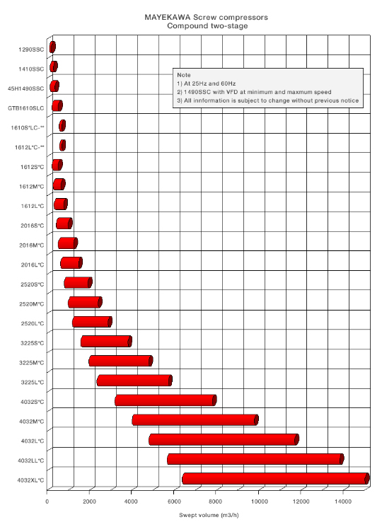
The 2-stage compression system, which has hitherto required two units of standard-type screw compressor for its embodiment, can now be realized by a single unit of compound 2-stage screw compressor. Generally, screw compressors use oil injection to keep discharge temperature at a low level during operation without loss of volumetric efficiency even at high compression ratios. It can, therefore, be operated with a single-stage compression system even at evaporative temperatures near -40 °C. However, for normal use at low temperatures, a 2-stage compression system is applied in order to improve kW/RT (ratio of power consumption versus refrigerating capacity). If the 2-stage compression system is configured with standard-type screw compressors, at least two screw compressor units need to be installed, one on the high-stage and the other on the low-stage, which inevitably requires double installation of the entire system including machinery, motors, utilities, etc. This 2-stage screw compressor is produced to solve this problem. It is a single unit that has two single-stage compressor units combined into one. The 4032**C model is currently the biggest size compressor in the compound 2-stage compressor C-series. In addition to general refrigeration systems and air conditioning systems, the 4032**C model has been used in variety process gas compression systems due to the ability to meet various requirements specifications, i.e., temperature conditions, pressure conditions, power conditions, etc. As a result, most of the products which have been manufactured and shipped until now, are special specification products. If there are different points of specifications between your purchased compressor and the standard specification compressor described in this manual, refer to the document showing specifications of your purchased compressor.
2.2 Model Designation of the Compressor
This manual describes 4032**C-*B*-51 and 4032**C-*B*-61 models. The meaning of the type designation, which is engraved on the MODEL column of the compressor nameplate, is as follows.
*4032**C-*B*-51/61
5: Power frequency (6: 60Hz)
1: Indicates that it is a motor directly connected type. * Unless specifically specified, machines manufactured in September, 2010 or after do not have this indication engraved on their nameplate.
- Vi (volume ratio) specified for the high-stage discharge port, standard value of which is L or M Means a booster (low-stage machine)
- Vi (volume ratio) specified for the low-stage discharge port, standard value of which is L or M
C Stands for Compound (compound 2-stage machine)
**Specifications of high-stage rotor length, which is L, M or S
**Specifications of low-stage rotor length, which is LL, L, M or S
32 High-stage rotor diameter of 250
40 Low-stage rotor diameter of 320
*4 Indicates working fluid (Example: N = Ammonia, F= Fluorocarbon, P = Propane, HE = Helium)
There are cases that the symbol indicating the special specification is engraved other than these. In such a case, refer to the specifications of each compressor.
2.3 Compressor Specifications
2.3.1 Specifications
Table 2-1 4032**C Screw Compressor Specifications (1/2)
Items Model
XLLLC LLLLC LLLC LLMC LLSC LLC
Product mass kg 12320 *Note1 11250 10500 10350 10150 9700
Low-stage swept volume @3550 min-1 /2950 min-1 m3/h 15600 /12900 13800 /11500 13800 /11500 13800 /11500 13800 /11500 11700
/9700
High-stage swept volume @3550 min-1 /2950 min-1 m3/h 6740 /5600 6740 /5600 5700 /4740 4760 /3960 3820 /3170 5700 /4740
Working fluid - Ammonia, Hydrofluorocarbon, Hydrocarbons, Other.
Design pressure MPa 2.6
Capacity control (Actual load) % 10 to 100
Rotation direction - Counterclockwise viewed from motor
Table 2-2 4032**C Screw Compressor Specifications (2/2)
Items Model
LSC MLC MMC MSC SLC SMC SSC
Product mass kg 9350 8900 8750 8550 8050 7900 7700
Low-stage swept volume @3550 min-1 /2950 min-1 m3/h 11700 /9700 9800 /8140 9800 /8140 9800 /8140 7800 /6480 7800 /6480 7800 /6480
High-stage swept volume @3550 min-1 /2950 min-1 m3/h 3820 /3170 5700 /4740 4760 /3960 3820 /3170 5700 /4740 4760 /3960 3820 /3170
Working fluid - Ammonia, Hydrofluorocarbon, Hydrocarbons, Other.
Design pressure MPa 2.6
Capacity control (Actual load) % 10 to 100
Rotation direction - Counterclockwise viewed from motor
Unless otherwise noted, the pressure unit MPa represents the gauge pressure in this manual.
For limits of working temperature and pressure, refer to Section2.3.2 "Operation Limits" in this Chapter.
For sizes of connecting piping, refer to Section 2.3.2 "Outer Dimensions" or Section 3..2.4 Table 3-1 " List of Connecting Pipes (Compressor)" in this manual.
2.3.2 Operation Limits
Table 2-3 Operation Limits of 4032**C
Items and Operation Limits
Maximum discharge pressure MPa 1.96
Minimum suction pressure MPa −0.080
Maximum intermediate pressure MPa 0.588
Minimum intermediate pressure - > Suction pressure
Oil supply pressure
・ Maximum journal lubrication pressure MPa Discharge pressure + 0.39
・ Minimum journal lubrication pressure MPa Discharge pressure +0.049 and
Suction pressure +0.49
・ Minimum oil injection lubrication pressure MPa Suction pressure +0.49
Maximum Suction temperature °C 85
Minimum suction temperature °C −60
Maximum low-stage discharge temperature °C 90
Maximum high-stage discharge temperature °C 100
Maximum oil supply temperature °C 60
Minimum oil supply temperature °C 30
Maximum male rotor rotation speed min-1 3600
Minimum male rotor rotation speed min-1 1450
Note: Unless otherwise noted, the pressure unit MPa represents the gauge pressure in this manual.
If operation at partial load, which is not greater than 30 % of the indicated load, is continued for a long time except when starting up the machine, abnormal noises or vibration may be generated. So avoid such operation.
Repeated startup and stop in a short period is harmful not for the startup devices and electric machinery but also for the compressor itself. For information on the start/stop limitations, refer to each instruction manual. Wait at least 15 minutes after stopping the compressor before restarting it.
2.3.3 Outer Dimensions
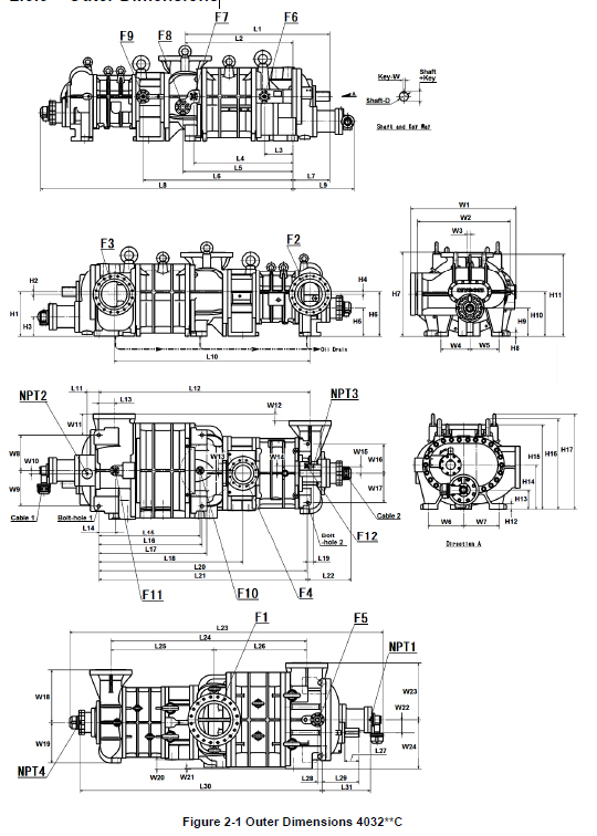
Table 2-4 4032**C Outer Diameter of Low-stage M Rotor and Shaft Key Size
Symbol in Figure 2-1 Location Qty Size (Length unit:mm)
Shaft-D Outer diameter of low-stage M rotor shaft 1 Φ 110 ±0.01
Key-W Shaft key width of low-stage M rotor shaft 1 32 0 -0.062
Shaft +Key Shaft key groove height of low-stage M rotor shaft - 117
Table2-5 4032**C Connecting Port Size Symbol in Figure 2-1 Location Qty Size
F1 Low-stage gas inlet port 1 ANSI #300 16”
F2 High-stage gas inlet port 1 ANSI #300 12”
F3 Low-stage gas outlet port 1 ANSI #300 12”
F4 High-stage gas outlet port 1 ANSI #300 8”
F5 Low-stage TPTB lubricating oil inlet port 1 ANSI #300 2”
F6 Low-stage Main bearing lubricating oil inlet port 1 ANSI #300 2”
F7 Low-stage Side bearing lubricating oil inlet port 1 ANSI #300 1”
F8 Oil injection inlet port 1 ANSI #300 2-1/2”
F9 High-stage journal lubricating oil inlet port 1 ANSI #300 2”
F10 Oil outlet port of low-stage suction cover 1 ANSI #300 1/2”
F11 Oil outlet port of low-stage bearing head 1 ANSI #300 1”
F12 Oil outlet port of high-stage suction cover 1 ANSI #300 1/2”
NPT1 Low-stage capacity control hydraulic pressure connecting port (Loading) 1 NPT 3/4
NPT2 Low-stage capacity control hydraulic pressure connecting port (Unloading) 1 NPT 3/4
NPT3 High-stage capacity control hydraulic pressure connecting port (Loading) 1 NPT 1/2
NPT4 High-stage capacity control hydraulic pressure connecting port (Unloading) 1 NPT 3/8
Cable1 Low-stage electric wires for unloader indicator connecting port (EPB-102) 2 PF 3/4
Cable2 High-stage electric wires for unloader indicator connecting port (EPB-102) 2 PF 3/4
Bolt-hole 1 Bolt hole for low-stage compressor leg 4 Φ39
Bolt-hole 2 Bolt hole for high-stage compressor leg 2 Φ33
Table 2-6 4032**C Outer Dimensions Unit: mm Symbol in Figure 2-1 Compressor Model
LLC LMC LSC MLC MMC MSC SLC SMC SSC
L1 1792.5 1792.5 1792.5 1684.5 1684.5 1684.5 1569.5 1569.5 1569.5
L2 1336.5 1336.5 1336.5 1228.5 1228.5 1228.5 1113.5 1113.5 1113.5
L3 354 354 354 354 354 354 354 354 354
L4 1229 1229 1229 1121 1121 1121 1006 1006 1006
L5 1364 1364 1364 1256 1256 1256 1141 1141 1141
L6 1855 1855 1855 1747 1747 1747 1632 1632 1632
L7 456 456 456 456 456 456 456 456 456
L8 3126 2990 2854 3018 2882 2746 2903 2767 2631
L9 759 759 759 759 759 759 664 664 664
L10 2426 2339 2251 2318 2231 2143 2203 2116 2028
L11 145 145 145 145 145 145 145 145 145
L12 2616 2529 2441 2508 2421 2333 2393 2306 2218
L13 190 190 190 190 190 190 190 190 190
L14 205 205 205 205 205 205 205 205 205
L15 1254 1254 1254 1146 1146 1146 1031 1031 1031
L16 1279 1279 1279 1171 1171 1171 1056 1056 1056
L17 1336.5 1336.5 1336.5 1228.5 1228.5 1228.5 1113.5 1113.5 1113.5
L18 1785.5 1785.5 1785.5 1677.5 1677.5 1677.5 1562.5 1562.5 1562.5
L19 70 70 70 70 70 70 70 70 70
L20 2576 2489 2401 2468 2381 2293 2353 2266 2178
L21 2586 2499 2411 2478 2391 2303 2363 2276 2188
L22 540 491 443 540 491 443 540 491 443
L23 3885 3749 3613 3777 3641 3505 3567 3431 3295
L24 2426 2339 2251 2318 2231 2143 2203 2116 2028
L25 1279.5 1192.5 1104.5 1279.5 1192.5 1104.5 1279.5 1192.5 1104.5
L26 1146.5 1146.5 1146.5 1038.5 1038.5 1038.5 923.5 923.5 923.5
L27 176 176 176 176 176 176 176 176 176
L28 59 59 59 59 59 59 59 59 59
L29 456 456 456 456 456 456 456 456 456
L30 3000 2864 2728 2892 2756 2620 2777 2641 2505
L31 598 598 598 598 598 598 503 503 503
W1 1305 1305 1305 1305 1305 1305 1305 1305 1305
W2 1150 1150 1150 1150 1150 1150 1150 1150 1150
W3 34 34 34 34 34 34 34 34 34
W4 360 360 360 360 360 360 360 360 360
W5 360 360 360 360 360 360 360 360 360
W6 440 440 440 440 440 440 440 440 440
W7 440 440 440 440 440 440 440 440 440
W8 440 440 440 440 440 440 440 440 440
W9 440 440 440 440 440 440 440 440 440
Symbol in Figure 2-1 Compressor Model
LLC LMC LSC MLC MMC MSC SLC SMC SSC
W10 38 38 38 38 38 38 38 38 38
W11 260 260 260 260 260 260 260 260 260
W12 84 84 84 84 84 84 84 84 84
W13 34 34 34 34 34 34 34 34 34
W14 95 95 95 95 95 95 95 95 95
W15 80 80 80 80 80 80 80 80 80
W16 360 360 360 360 360 360 360 360 360
W17 360 360 360 360 360 360 360 360 360
W18 650 650 650 650 650 650 650 650 650
W19 500 500 500 500 500 500 500 500 500
W20 110 110 110 110 110 110 110 110 110
W21 15 15 15 15 15 15 15 15 15
W22 160 160 160 160 160 160 160 160 160
W23 700 700 700 700 700 700 700 700 700
W24 605 605 605 605 605 605 605 605 605
H1 550 550 550 550 550 550 550 550 550
H2 30 30 30 30 30 30 30 30 30
H3 240 240 240 240 240 240 240 240 240
H4 30 30 30 30 30 30 30 30 30
H5 348 348 348 348 348 348 348 348 348
H6 550 550 550 550 550 550 550 550 550
H7 1055 1055 1055 1055 1055 1055 1055 1055 1055
H8 50 50 50 50 50 50 50 50 50
H9 348 348 348 348 348 348 348 348 348
H10 550 550 550 550 550 550 550 550 550
H11 1030 1030 1030 1030 1030 1030 1030 1030 1030
H12 70 70 70 70 70 70 70 70 70
H13 240 240 240 240 240 240 240 240 240
H14 550 550 550 550 550 550 550 550 550
H15 1050 1050 1050 1050 1050 1050 1050 1050 1050
H16 1120 1120 1120 1120 1120 1120 1120 1120 1120
H17 1180.5 1180.5 1180.5 1180.5 1180.5 1180.5 1180.5 1180.5 1180.5
2.4 Compressor Structure
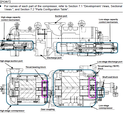
Figure 2-2 4032**C Screw Compressor Sectional View
The 4032**C model, a compound 2-stage compressor, consists of two compressors, (i) a low-stage compressor which suctions gas, working fluid, from the refrigerating unit and compresses (pressure-raises) the gas and (ii) a high-stage compressor which furthermore compresses the gas that has been pressure-raised by the low-stage compressor and sends the resulting gas to the equipment side. In each casing (low-stage, high-stage), two screw rotors are supported on both ends by bearings. They are meshed with each other in a joint assembly. These two screw rotors are a set of a male rotor having 4 protruding lobe profiles (M rotor) and a female rotor having 6 concave lobe profiles (F rotor). They conduct compressing according to the mechanism explained below. The standard compressor's M rotor is driven by a 2-pole motor; it operates at 3000 min-1 (50 Hz) or 3600 min-1 (60 Hz). F rotor operates at 2000 min-1 (50 Hz) or 2400 min-1 (60 Hz), conforming to the operation of M
rotor. * The actual speed of a motor is less than its calculated speed (synchronous speed). This difference is
caused by slipping of the motor rotor. The shaft of the low-stage compressor's M rotor which is linked with the motor has a shaft seal block that keeps gas and lubricating oil from leaking from inside the compressor. For high efficient operation, the 4032**C model has a capacity control mechanism for coping with load change on the low-stage, and a capacity control mechanism for reducing startup load on the high-stage.
2.5 Mechanisms
2.5.1 Basics of the Screw Compressor
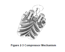
The screw compressor is categorized as a positive displacement rotary compressor. As shown in Figure 2-3, the refrigerant (gas) is continuously compressed by the 3-dimensional spaces that are formed by a pair of male and female screw rotors (with different sectional profiles) and the casing, as the spaces change continuously. The rotor having 4 protruding lobe profiles is called a male rotor or M rotor, and the rotor having 6 concave lobe profiles is called a female rotor or F rotor. In this manual, they are referred to as M rotor and F rotor. The compressor is driven by the motor connected to the shaft of the M rotor.
2.5.2 Suction Process
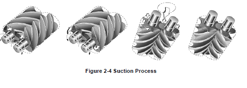
As shown in Figure 2-4, the rotors with different lobe profiles are engaged. As the rotors turn, the volume between the M and F rotor lobe profiles and the compressor casing gradually increases starting from the suction side. As the rotation continues, at a certain point when the volume reaches its maximum, the rotors isolate the gas (volume), which is enclosed by the rotors and the compressor casing, from the suction port and then continues rotation.
2.5.3 Compression Process
As the rotors rotate further, the volume between the rotor lobes decreases while the sealing line moves toward the discharge side, which compresses the trapped refrigerant gas.
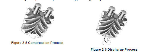
2.5.4 Discharge Process
The volume between the rotor lobes decreases to a level predetermined by the discharge port. With the rotations of the rotors, the compressed refrigerant gas is pushed out to the discharge port.
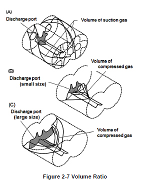
2.5.5 About Volume Ratio (Vi)
Volume ratios (Vi) of C-series screw compressors are indicated in performance tables or catalogs by using port symbols L and M. The volume ratio represented by each symbol is as follows: L=2.63, M=3.65 Which volume ratio (L or M) should be used is decided according to operating conditions. If the compressor is used with a volume ratio that does not match operating conditions, operation will go inefficiently wasting the power. The relationship between volume ratios and generally used compression ratios is as follows:
As Vi is affected by the constant of the refrigerant gas, its value that corresponds to the compression ratio will change depending on the refrigerant gas.
(A) Properly adapted Vi to load condition
2.5.6 Capacity Control Mechanism
The capacity control mechanism, by moving a slide valve, lets suction gas (immediately before compressed) bypass and advance to the suction side, to help shorten the rotor portion used for compression. The slide valve is located at the bottom of the casing in which the rotors mesh together, and is constructed to move parallel to the rotor shaft. This movement is changed by a cam mechanism into rotation movement. Its position (namely, capacity control ratio) is indicated externally and, at the same time, fed back to the automatic control circuit by changing the electric resistance. 4032 ** C compressor, has a capacity control mechanism for reducing start-up load on the high-stage, and a capacity control mechanism for coping with load change on the low-stage.

2.5.7 Bearing and Balance Piston
For the load acting on the rotor perpendicular to the shaft, sleeve-type white metal-lined bearing is used. For the load acting along the shaft direction, the low-stage compressor uses tilting pad bearings while the high-stage compressor uses angular ball bearings in the front combination. In case of API 619 compliance is required and/or special gas component is contained in the working fluid, the high-stage compressor also uses tilting pad bearings for the load acting along the shaft direction. Special care is taken to cope with the load acting along the shaft direction. Because the M rotor is a kind of helical gear and also because the thrust force produced by discharge pressure is larger than that for F rotor, the load applied onto the M rotor is reduced by using not only a thrust bearing but also a balance piston that applies pressure from the opposing direction.
2.5.8 Shaft Seal
A mechanical seal assembly, which has balance type double seal structure is used as a shaft seal. A mechanical seal assembly has two sliding seal blocks consisting of rotating rings and stationary rings on inner machine side and atmosphere side. Those sliding seal blocks prevent leakage of working fluid (refrigerant) and oil from M rotor shaft. For example, the BBDE (Balance Bellow Double Seal) which is currently used as standard seal, employs stationary ring (mating ring) made from carbon, rotating ring made from SiC, and O-rings for the packing.
2.6 Gas and Oil Flow
The compression process of the screw compressor is as described in the preceding paragraphs. Gas of the compound 2-stage screw compressor 4032**C is sent from the evaporator, and passes through the suction strainer and check valve. It is drawn in from the upper central area (1) of the compressor, compressed at the low-stage side (2), and then discharged at (3). (3) and (4) are connected with a pipe. At the mid point of the pipe, that gas is mixed with the gas from liquid cooler which was used for supercooling. Gas compressed at the low-stage is, while kept mixed with lubricating oil, suctioned from (4) into the high-stage. After being further compressed at (5), the gas with lubricating oil is discharged from (6), and is sent to the condenser via an oil separator. Even if without intermediate gas cooling, oil provides cooling effect. So, the high-stage discharge temperature is maintained at a temperature not higher than 90 °C.
Oil Supply Route
As shown in Figure 2-12, oil supply route for the low-stage is split into six flows including the flow to the shaft seal block lubrication. After completing each role, the oil flows to the high-stage via the low-stage rotor messing part. Oil supply system in the high-stage is split into three flows. Eventually, the oil mixed with compressed gas and the oil from the low-stage are discharged from the compressor via the high-stage rotor messing part. In standard configuration, oil injection is not performed at the high-stage.
Chapter 3 Installation
3.1 General Precautions for Installation
This chapter (Installation) assumes that the compressor is installed to a standard refrigeration/ cold storage/gas compression package unit. If the package unit you are actually using is not the standard type refrigeration/cold storage/gas compression package unit, prepare a proper installation manual by referring to the description in this chapter and paying due consideration to safety, before installing the compressor. If there are any questions, please contact our local sales offices or service centers.
In some cases, it may be required that installation is performed by qualified personnel. Make sure that the work is performed by qualified personnel in compliance with local laws, ordinances and other regulations/requirements.
Before installing the compressor, please read this chapter and related documents attentively and fully understand their contents.
Electrical works should be performed only by electrical engineers.
3.2 Installation Works
3.2.1 Unpacking
Confirm whether a compressor does not have abnormality including the damage.
If there are abnormalities or deficient parts on the compressor, please contact our sales offices or service centers immediately.
Unnecessary packing materials should be discarded according to the laws and ordinances, or your company's rules.
3.2.2 Storage
If you need to store the compressor before installation, perform the followings.
Store it indoors.
Infuse nitrogen gas into the compressor and seal it. (Pressure: Approximately 0.15 Mpa )
3.2.3 Transportation
Dropping of the lifted compressor may cause death or serious injury to the worker. Do not allow anyone to be under the lifted compressor.
1. For lifting the compressor within the safety limit, use lifting equipment and tools appropriate for the mass of compressor.
2. Secure sufficient space for safe lifting.
3. Always check the wire ropes before using them. Thoroughly check the wire ropes for problems such as kinks, knots and broken strands. Do not perform lifting before confirming the safety of the wire ropes. If you cannot make a correct evaluation or judgment, entrust an expert to check.
4. To lift the compressor, attach the wire ropes to the appended eye bolts by using appropriate shackles and hooks. Refer to Figure 3-1in next page. Use the eye bolts only for lifting the compressor. Do not use the eye bolts when lifting the compressor together with additive equipment.
5. Check the transportation route to make sure it is free of obstacles in consideration of the compressor size.
6. Before lifting, check that the hook is located above the gravity center of the compressor.
7. Direct all the workers to stay clear of the work site before lifting.
8. Before lifting the compressor, alert all workers in area of dangers during lifting process by signal (such as calling at the beginning of the work or making a signal by hand). Do not lift the compressor unless the signals (such as calling out or hand signals) are completely understood by the workers at site.
9. Slowly reel up the wire ropes until immediately before the compressor leaves the ground.
10. Then, reel up the wire ropes a little further until the compressor is slightly up away from the ground. Check that the compressor is not tilted. If the compressor is tilted, return the compressor to the ground and correct the tilt by adjusting the wire ropes. After that, restart the lifting operation.
11. Be sure to lift up the compressor slowly. If it is lifted rapidly, it may damage the lifting tools such as wire ropes or a part of the compressor.
12. When the lifting work starts, observe to see if wire ropes and lifting tools are normal. Be sure that the compressor is not tilted.
13. When moving the lifted compressor, always use guiding ropes.
14. When moving the compressor, turn away workers from the movement direction and check safety.
15. Do not lift the compressor above the safety passage unless absolutely necessary.
16. Do not lower the compressor on the safety passage. Always keep the safety passage free of obstacles.
17. Remove any obstacles before lowering the compressor onto the ground. The compressor should not be tilted or unstable.
18. Before lowering the compressor, announce to the workers around the working area in advance.
19. When lowering the compressor onto two or more blocks, align the tops of blocks so that the compressor becomes stable horizontally on them.
20. Slowly lower the lifted compressor so that it is not damaged by shock.
Outer Dimensions, Mass and Lifting Position

3.2.4 Preparation for Installation
Installation Space Secure sufficient working space for easy operation, cleaning, maintenance, and inspection.
Illumination Prepare illumination devices which allow easy operation, cleaning, maintenance, and inspection.
Ventilation If natural ventilation is insufficient, install ventilation fans according to the relevant regulations.
Table 3-1 List of Connecting Pipes (Compressor)
Item Size Φ A Φ B Φ C Φ D E UNCBolt Size Qty (Bolt)
Suction gas inlet ANSI #300 16” 650 571.5 470 400 65 1-1/4-7 20
High-stage gas inlet ANSI #300 12” 521 451 381 300 60 1-1/8-7 16
Low-stage gas outlet ANSI #300 12” 521 451 381 320 60 1-1/8-7 16
High-stage discharge gas outlet ANSI #300 8” 381 330 270 200 50 7/8-9 12
Lubricating oil inlet for low-stage TPTB ANSI #300 2” 165 127 92 50 35 5/8-11 8
Lubricating oil inlet for low-stage main
bearing ANSI #300 2” 170 127 92 40 35 5/8-11 8
Lubricating oil inlet for low-stage side
bearing ANSI #300 1” 156 89 51 30 35 5/8-11 4
Oil inlet for oil injection ANSI #300
2-1/2” 190 149 105 65 40 3/4-10 8
Lubricating oil inlet for high-stage bearing ANSI #300 2” 165 127 92 45 35 5/8-11 8
Oil outlet of low-stage suction cover ANSI #300 1/2” 95 66.5 35 18 25 1/2-13 4
Oil outlet of low-stage bearing head ANSI #300 1” 124 89 51 23.5 35 5/8-11 4
Oil outlet of high-stage suction cover ANSI #300 1/2” 95 66.5 35 18 30 1/2-13 4
Lubricating oil inlet for low-stage capacity
control (load) NPT 3/4 - - - - - - -
Lubricating oil inlet for low-stage capacity
control (unload) NPT 3/4 - - - - - - -
Lubricating oil inlet for high-stage capacity
control (load) NPT 1/2 - - - - - - -
Lubricating oil inlet for high-stage capacity
control (unload) NPT 3/8 - - - - - - -

3.2.5 Installation
3.2.5.1 Installation
Check that the surface of the package unit, where the compressor is to be installed, is even and horizontal. If it is uneven and non-horizontal, tightening the bolts may lead to compressor deformation, which may prevent normal operation.
3.2.5.2 Shaft Alignment between the Compressor and Driving Machine
Turn off the main power and control power of the driving machine before shaft alignment work between the compressor and the driving machine. Be careful so that the power of instruments does not turn on during shaft alignment work. If the power turns on during shaft alignment work, the driving machine starts moving and there is a risk of being entangled with the rotating shaft.
At the time of turning ON/OFF each electric power breaker, make sure to prevent electric shock.
For shaft alignment work between the compressor and driving machine, use designated tools in normal condition. If a worn or damaged tool or a tool unsuitable for the work is used, there is a risk of being injured.
In the case shaft alignment between this product and the driving machine, be sure that the deviations within the range shown in the Table 3–2. However, if alignment tolerance of the driving machine side is more stringent than Table 3-2, please adjust to the request within the allowable value of the driving machine side.

3.2.5.3 Piping Connection
Refrigerant Piping Observe the following when connecting the refrigerant piping to the compressor.
The compressor is one of the few devices installed within the package unit that have moving components. These moving components are adversely affected by foreign substances within the system (scale, dust, spatter, etc.). Therefore, when connecting the piping, do not allow any of such foreign substances to enter inside.
Some compressors (mainly those for export) are charged with nitrogen gas to prevent rust. Be sure to release the pressure before starting piping work.
Be sure not to allow moisture to enter the piping. There is a high probability that it will cause trouble after the start of operation. Be sure to assemble piping when it is dry.
Cover flanges are attached to the compressor's low-stage gas outlet and high-stage gas inlet. After installation, be sure to attach piping (intermediate piping) that links the both connection ports.
Improper piping may cause operating problems such as oil not returning to the compressor or liquid flow-backs.
When connecting the piping to the compressor, use piping that is the same size as the compressor connection port. If the pipe size of the piping is smaller than the compressor connection port, the flow of lubricating oil or refrigerant will be obstructed leading to problems.
Do not let the mass of the piping connected to the compressor applied onto flanges or joints. Be sure to prepare proper supports for piping.
3.2.5.4 Equipment and Devices for Protection of the Compressor
Oil Filter According to the requirements of the use of the package unit or the standard to apply, install an oil filter of appropriate filtration precision in the lubrication system of the compressor. In case of general applications such as closed-cycle refrigeration systems, we recommend to use an oil filter with beta ratio in the range of β20 ≥ 150 that conforms to requirements of NAS 1638 class 8 or ISO 4406 17/15/13. When the package unit requires API 619 4th/5th edition conformity, use an oil filter with beta ratio in the range of β10≥200. The oil filter may be clogged just after test operation. We recommend installing two oil filters in parallel. This will enable replacement of either filter during operation.
Oil Heater for Oil Separator To preserve the temperature of the lubricating oil before starting the compressor, install an oil heater on the oil separator. Make sure to install a protection function (thermostat, etc.) to prevent overheating.
Suction Strainer When compatible (inter-soluble) oil is used, the mesh size of suction strainer should be not less than 200 meshes. When incompatible (non- inter-soluble) oil is used, it should be not less than 100 meshes. For details about compatible and incompatible oils, refer to Section 4.1 "Lubricating Oil (Refrigerant Oil)" in this manual Chapter 4. During the commissioning, small particles and scale may come from the system. We recommend installing a finer filter temporarily.
Compressor Protective Devices (Safety Devices) To protect the compressor, install the necessary protective devices as described in Section 1.4.3 "Compressor Protective Devices" in this manual Chapter 1.
3.2.6 Airtightness Test
Perform an airtightness test on the package unit before starting commissioning. To prevent water entry in the package unit, use nitrogen gas or dry air for the airtightness test.
3.2.7 Lubricating Oil Charge
TO select the lubricating oil to be used, refer to Section 4.1 "Lubricating Oil (Refrigerant Oil)" in this manual Chapter 4.
When refilling lubricating oil, ensure that it is clean and does not contain foreign matters.
Be careful that air and water are not mixed in when refilling.
To ensure that the lubricating oil does not absorb air moisture, keep it indoors in an airtight container until use.
3.2.7.1 Initial Charge of Lubricating Oil
Depending on the package unit configuration and operating condition, specify the procedure, method and amount of the initial charge of lubricating oil, and make sure to provide users of this product with such information. In determining the procedure and work procedure, please care oil is to be filled in the oil filter and oil cooler always.
3.2.7.2 Additional Charge of Lubricating Oil
Specify the procedure of the additional filling of lubricating oil based on the configuration of the package unit, and make sure to provide users of this product with the information.
3.2.8 Charge of Refrigerant
Depending on the use working fluid and equipment configuration of your package unit, specify the work procedure that considered safety enough, and conduct the refrigerant initial filling work accordingly. In addition, specify the procedure of the additional filling of refrigerant, make sure to provide users of this product with the information.
3.2.9 Check after Installation
Depending on the package unit to which this product is installed, formulate the necessary confirmation items and methods for package unit after installation and conduct them accordingly before the commissioning. In addition, make sure to record and keep the results of your confirmation.
Chapter 4 Compressor and Package Unit Operation
4.1 Lubricating Oil (Refrigerant Oil)
Lubricating oil (Refrigerant oil) management is very significant to keep the compressor in a good operating condition. Take the following notes when managing lubricating oil.
4.1.1 Precautions for Selecting the Lubricating Oil
Selection of the lubricating oil should depend on the type of the refrigerant, the type of the evaporator used with the compressor, and the conditions under which the compressor is operated. Also to be considered when selecting lubricating oil are the properties of the oil that include not only the viscosity but also such characteristics as solubility in refrigerant, separability from refrigerant, low temperature fluidity, high temperature thermal stability, etc. We therefore recommend contacting our sales offices or service centers for choice of a specified brand for your system.
Lubricating oil used for compressors must have a viscosity appropriate for lubricating the bearings and other components in the compressors. The viscosity to be considered in this case should be the viscosity the oil shows at the oil inlet of the compressor. The viscosity of the lubricating oil significantly changes depending on the type of the refrigerant used in combination with the oil. If the refrigerant dissolves in the oil (or the oil and refrigerant are inter-soluble), the viscosity of the oil drops to a level remarkably below the level required for operation of the compressor under some operating conditions. On the contrary, if the refrigerant does not dissolve in the oil (or the oil and refrigerant are non-inter-soluble), the viscosity may become too high when the supply oil temperature is low. For this reason, the lubricating oil must be selected such that it is supplied to the compressor with an appropriate viscosity (kinematic viscosity of 13 - 40 mm2/s) in the operating state.
The circulation of the lubricating oil for the entire system must be considered. After lubricating and cooling each part of the compressor, the lubricating oil is discharged with refrigerant gas. Most of the oil which is discharged from this compressor is trapped by the oil separator and is cycled to the compressor. A small quantity of refrigerant oil goes to the condenser and the evaporator. The lubricating oil is required to have sufficient fluidity and stability inside parts with different temperatures.
Note that some lubricating oils are incompatible with a certain type of refrigerant. The caution below is an example case that is required especially attention.
Be careful since polyolester synthetic oil (POE) cannot be used with ammonia refrigerant.
4.1.2 Change of Lubricating Oil Brand
When changing the lubricating oil brand in currently use due to some reason, attention must be paid to the following points.
The change of lubricating oil brand may cause problems in operating conditions and the compressor. When changing the lubricating oil brand in use, make sure to contact us because appropriate steps must be surely followed.
Package unit composition differs depending on the characteristics of lubricating oil (inter-soluble/non-inter-soluble with refrigerant). As a general rule, changing inter-soluble oil to non-inter-soluble oil or vice versa is not allowed.
Lubricating oil contains various additives to fulfill necessary lubricating conditions. Types of additives and their mixing ratio depend on each oil brand. We, therefore, recommend to avoid mixed use of different brands of lubricating oil. If mixed brands of lubricating oil are used, the different additives in the lubricating oil may react with each other and produce foreign substances like slurry.
If it is necessary to change the brand of lubricating oil, collect as much as oil as possible from the compressor as well as from the condenser, evaporator, and all other refrigerating unit components before charging the new lubricating oil. After 100 to 200 hours of operation, replace the oil again.
If lubricating oil manufacturers differ, contact both of them and inquire whether the changing is appropriate. The same confirmation is required for changing the brand even if it is of the same manufacturer.
There is no problem in changing the viscosity level within the same brand. However, make sure that the viscosity grade will not cause problems during operation. (Example : SUNISO 3GS→SUNISO 4GS)
4.1.3 Precautions for Handling lubricating oil
When refilling lubricating oil, ensure that it is clean and does not contain foreign matters.
Be careful that air and water are not mixed in when refilling.
To ensure that the lubricating oil does not absorb air moisture, keep it indoors in an airtight container until use.
4.1.3.1 Precautions for Handling Polyalkylene Glycol (PAG)
PAG oil is much more hygroscopic than mineral oils and any moisture mixed in the oil may lead to rust, corrosion and wear within the package. When handling PAG oil, pay special attention to the following points.
Do not perform oil charging in rainy weather or at a place with high humidity to prevent absorbing moisture.
Before charging, remove as much moisture as possible from the system by exhausting it with a vacuum pump for a sufficient length of time and leaving the system in vacuum condition overnight.
Do not open the lid of pail (oil container) until just before charging. Once the can is opened, finish the oil charge as quickly as possible. (Finish the charge of a single can of oil within 15 minutes.)
Cover any gaps between the pail opening and the charge hose so that foreign substances or moisture cannot enter. A more effective way is to substitute any space inside the pail with nitrogen gas .
Always charge all oil from the pail. Even if some oil remains, do not use it subsequently.
If any oil drops on a painted surface, wipe it away as soon as possible. Otherwise the paint may come off.
4.1.3.2 Precautions for Handling Polyolester (POE) Oil
This type of oil has high hygroscopicity as polyalkylene glycol, and also exhibits hydrolyzability under high temperature environments. Moisture entry must be avoided. Therefore, special attention must be paid as with PAG when handling POE.
Finish the charging in as short a time as possible after opening the pail to minimize exposure to air.
Make sure that all oil in a pail is used in a single charging. Any remaining oil must be stored indoors with the can lid closed tightly. Do not attempt to store it for a long time.
Because POE can hydrolyze, make sure to perform an oil analysis regularly in the package to see if any abnormal conditions are present.
4.1.4 Lubricating Oil Management Criteria
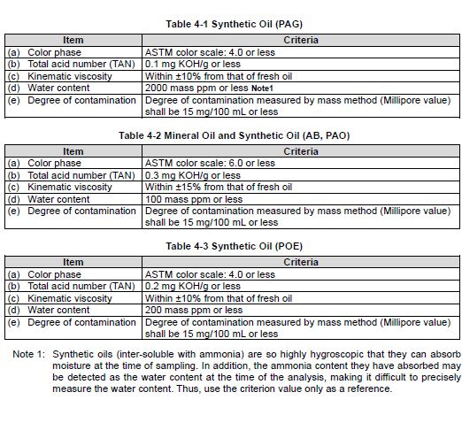
Lubricating oils that are managed by the criteria are classified into the following categories:
(1) Synthetic oils: Polyalkylene glycols (PAG)
(2) Mineral oils: Naphthenic base oils and paraffinic base oils
(3) Synthetic oils: Alkylbenzene (AB) and Polyalphaolefine (PAO)
(4) Synthetic oils: Polyolesters (POE)
Oil sampling and analysis is recommended every six months.
If the following control criteria are not satisfied, replace the oil.
◆ Note that the water content of PAG shall be excluded from the above oil replacement criteria. Refer to the Note *1 in the table below. The analysis items and the criteria are shown in the following tables. Please note that these management criteria may be changed without notice.
4.1.5 Lubricating Oil Replacement Timing
As the oil can easily be contaminated and degraded relatively quickly during the initial operation due to scales and deposits remaining in piping and vessels, be sure to sample and analyze the oil after 500 hours of operation. If it is found as a result of the analysis that the criteria given in Tables 4-1 to 4-3 are not satisfied, the oil must be replaced.
4.1.5.2 During Normal Operation
Lubricating oils will degrade gradually as the system is operated over time. The rate of degradation depends on the operating condition, type of oil and amount of foreign matters and moisture contained in the oil. The lubricating oil must be sampled and analyzed every six months. If it is found as a result of the analysis that the control criteria given in Tables 4-1 to 4-3 are not satisfied, the oil must be replaced. If the oil filters are frequently clogged or the oil color quickly becomes darker and unclear, replace the oil after removing the cause of the problem.
4.2 Precautions for Operation
If the package unit is used in the refrigeration cycle, please keep in mind the contents of this section in particular.
4.2.1 Prevention of Liquid Flow-back Operation
Liquid flow-back is a phenomenon where refrigerant that did not completely evaporate with the gas reaches the compressor. Liquid flow-back may cause insufficient lubrication of the compressor, abnormal vibrations and noises, and abnormal foaming of lubricating oil (too much oil loss). To prevent liquid flow-back, appropriately adjust the expansion valve to the evaporator and/or liquid cooler. In addition, special attention must be paid to the suction pipe line connection way to the system and means of starting up the compressor after a long time of stoppage.
4.2.2 Purging of Non Condensable Gases
Any non condensable gas in the system may cause the compressor discharge pressure to rise higher than the refrigerant saturation pressure that depends on cooling water temperature of condenser. This is caused by the non condensable gas staying in the condenser which deteriorates the heat exchange performance. If the vacuum pumping performed upon initial installation or maintenance is insufficient or the suction pressure is lower than the atmospheric pressure to suck air if the suction pipe had a leak, non condensable gases accumulate in the condenser. When a considerable amount of non condensable gases accumulate in the condenser, the compressor load increases and finally the motor overcurrent alarm may occur. In such a case, purge any non condensable gas from the condenser.
Some types of refrigerants may have bad smell, toxicity, and/or flammability. In a airtight space such as a machine room, oxygen shortage may occur due to high concentration of the refrigerant gas. Maintain sufficient ventilation while working.
When handling fluorocarbon refrigerants, remember that they are prohibited from being purged into air by law.
1. When the compressor is stopped, allow the cooling water to flow to the condenser and check that there is no difference in water temperature between the inlet and outlet. If any difference is present between the inlet and outlet water temperatures, keep the cooling water flowing until the temperature difference is eliminated.
2. Measure the pressure of the condenser and compare it with the refrigerant saturation pressure depending on the cooling water temperature.
3. If the condenser pressure is higher than the refrigerant saturation pressure by 0.05 MPa or more, purge any non condensable gases.
4.3 When Stopping the Compressor for a Long Time
Before stopping the compressor for a long time, make sure to perform the following steps.
Turn off the motor main power.
Turn off the oil heater power and the control power.
Close the suction stop valve and discharge stop valve.
If an economizer or liquid injection is used, close the stop valve located at the compressor inlet.
If the operation stop period is 1 month or longer, perform the following check.
Operate the oil pump for 10 seconds per week. After that, rotate the compressor shaft (10 rotations or more).
Measure the system pressure once per month.
Check for refrigerant leak once per month.
When restarting the compressor after an operation stop period of 1 year or longer, check the system for refrigerant leak and analyze the lubricating oil. If it is found as a result of the analysis that the control criteria given in Section 4.1.4 Tables 4-1 to 4-3 are not satisfied, the oil must be replaced. Also check the motor insulation resistance. Supply power to the oil heater at least 1 day before operation start. Before starting the operation, confirm that the refrigerant is not condensed in the package by checking the package temperature and pressure.
Chapter 5 Maintenance and Inspection
5.1 Precautions for Maintenance and Inspection
When entering the machine room for maintenance services, ensure that sufficient ventilation has been started and measure the oxygen concentration so that there is no risk of oxygen deficiency. The ventilation must be continued steadily until the work is completed.
For performing the inspection work, be sure to prepare safety shoes, protective glasses, gas mask and other proper protective equipment and do not fail to use them whenever they are required.
After stopping the machine and before working on a regular inspection or overhaul, be sure to shut off the main motor power, control power, and other power to each equipment and valve. After they are shut off, be sure to make the switches inoperable by others. Also, be sure to attach notification tags to prohibit operation (lock-out/tag-out).
When any manual stop valve has been closed, be sure to make the valve inoperable by others and put a notification tag to prohibit the operation (tag-out).
When the compressor is to be overhauled, check that the internal pressure of this product is at the atmospheric pressure before starting the work.
When using lifting devices, e.g. a crane, etc. and/or lifting tools, ensure that they can sufficiently withstand the load.
When lifting a heavy load object, do not allow anyone’s body to put under it.
The work to turn each power supply ON/OFF or operate a lifting unit must be exclusively performed by qualified personnel.
When using electric tools, ensure that they are properly managed in accordance with each instruction manual. Especially before using and while using, be sure to follow the care instructions on the safety of each instruction manual.
Be sure to use only genuine parts for replacement. Using parts that are not genuine can cause damage to this product or other devices during operation.
Do not convert or modify this product or its components without prior permission from MAYEKAWA. Otherwise, it can lead to an unexpected accident.
Exercise sufficient care for handling a heavy load, and use such a lifting device as a crane or work with an adequate number of personnel commensurate with the magnitude of the weight. Also, be sure to use stud bolts (safety retention bolts) and other support tools for the work. Neglecting the above warning can lead to low back pain of the worker or injury due to dropping of the parts.
If two or more people are to work together, be sure to clearly define the work procedures to
share a common understanding among all workers before performing the work.
Not only the work to turn each power supply ON/OFF or operate a lifting device, but also any type of work requiring qualification must be exclusively performed by qualified personnel.
When checking the operation data of units and executing other daily maintenance services, pay particular attention to avoid touching the area heated to a high temperature causing skin burns or inadvertently moving the handle of a valve leading to an erroneous operation.
In the disassembly/inspection workplace, secure a sufficient space for temporary storage of the removed parts and tools, replacement parts, and for the disassembling work as well as safety passages, and then put up necessary off-limit signs.
In the workplace, secure a sufficient space and refrain from putting tools directly on the floor or from haphazardly laying wires.
Keep the floor clean all the time. Leaving the floor smeared with oil and the like causes it to be slippery and may result in the fall and injury of personnel. Thus, do not leave it but wipe it off right away.
Make sure that the temperature of the high temperature sections such as head covers and discharge lines has been cooled down to normal ambient temperature, before working on them.
When disassembling and reassembling the compressor, use the specified tools properly. Before starting to use those tools, gain the full understanding of their characteristics and the method for use.
During the maintenance service, keep the tools clean all the time. Using those tools smeared with oil increases the risk of slip and fall, leading to an injury. Also during the service, there is a risk of foreign matters intruding inside the compressor to cause its damage.
Parts are slippery with oil. Fully watch out for the risk of any object falling down. Pay attention to any parts falling down, which could lead to personal injury.
Before disassembly, inspections, and handling of the compressor, sufficiently understand the disassembly and assembly procedures. This manual is not intended to provide complete disassembly and assembly procedures for the compressor. Instead, it describes only the important points in relation to the maintenance service of the compressor.
If complete disassembly and assembly of the compressor are required, please contact your nearest sales office or service center of MAYEKAWA.
When removing a part, be careful not to damage it.
Place the removed parts on a clean workbench in an orderly manner.
For cleaning parts, use kerosene and/or machine parts cleaner.
Washed parts shall be dried by compressed air or wiped up using clean cloth. Do not use synthetic textiles or woolen textiles to prevent fibers from attaching the parts.
When separating the assembled compressor casings, sometimes it is difficult to separate them due to the gasket stuck. In such a case, never hammer in a screw driver or flat chisel into the gap. Screw jack bolts using the screw holes to separate the casing each other. When some gap is observed between them, use a scraper to remove one side of the gasket from the surface.
Removed bolts from each part should be classified into each used section to prevent confusion.
5.2 Maintenance and Inspection List
5.2.1 Daily Management
For the purpose of daily maintenance, check the items listed in Table 5-1 "Daily Inspection Item" and record the results. Regularly recording the daily operational data in an operation log makes it possible to detect any significant change in the system. This practice is particularly effective in preventing possible failures of the compressor. It is particularly important to keep track of the records that indicate the relationship between the temperature and pressure, as it is closely related to the evaporation and condensation of the refrigerant, in quickly finding any abnormal condition of the compressor or the system. Keeping an operation log in this way can facilitate the efforts to properly track down the cause of failure or accident that may occur in the compressor or the system, making it easier to quickly and accurately deal with the situation.
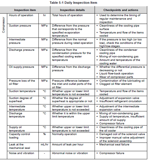
■ Unless otherwise specified, the pressure unit "MPa" represents the gauge pressure in this manual.
■ Daily Maintenance Items
1. Oil level height of the lubricating oil If the oil level of the oil separator has reached the lower limit, charge the lubricating oil.
2. Oil filer element replacement Replace the oil filter element if the pressure difference between the inlet and outlet ports of the oil filter is 0.1 MPa or more. During the period of initial operation, the pressure difference between the inlet and outlet ports of the oil filter can quickly become large.
3. Cleaning of suction strainer Inspect the suction strainer when the operating hours of the compressor from the initial operation starting has exceeded 500 hours. If the filter used is a temporary filter for initial operation, remove the filter. Also, as it is common that the differential pressure across the suction strainer can become large in a short period of time, inspect and clean the suction strainer if the differential pressure is large.
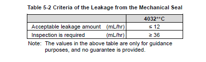
4. Amount of oil leak from the mechanical seal If the amount of oil leak from the mechanical seal is considered excessive, check the amount of oil leak per hour. The table below shows the guideline on the acceptable amount of oil leak and the amount that requires inspection. If any damage is found on the mechanical seal in the inspection, be sure to replace it.
5. Contamination on the cooling water side of the condenser and oil cooler cooling pipe. The degree of contamination and clogging of the cooling pipe can significantly vary depending on the quality of the cooling water. If any gradual increase in the oil temperature and/or the discharge pressure is observed during the initial period of operation, check and clean the cooling water side of the oil cooler and the condenser regardless of the inspection schedule.
5.2.2 Periodic Inspection
Conduct inspection for the following items according to the specified schedule. In addition, observe relevant laws and regulations on the inspections and recording of the results that are provided for other related items such as any safety devices (e.g. gas leak detectors), or other utility (gas/electricity) protection devices that constitute the package unit together with the compressor.

5.2.3 Guidelines for the Timing of Compressor Overhaul
While the overhaul interval for the compressor depends heavily on the conditions of use, type and condition of the refrigerant and oil, the package unit, and other factors, the table below shows the recommended interval of overhaul, as a guideline.
Please Contact SCS Screw Compressors Specialist @ 210-389-4907
5.3 Compressor Disassembly Preparation
Although screw compressors are very reliable machines, it is still necessary to perform overhaul to inspect internal parts after a certain period of operation. This chapter 5 explains the essential points of disassembly methods, where to inspect on parts, and reassembly procedure of the compound 2-satge screw compressor 4032**C.
In principle, overhauling of the screw compressor that require complete disassembly should be performed in the maintenance factory. If you must do the overhaul work at the installation site due to unavoidable reasons, use the methods described in the following paragraphs.
However, please note that regular overhaul work requires removal of the compressor from the base frame. And then, the compressor should be placed on a work bench which has properly size area to disassembling the compressor.
When moving the compressor from the unit base to the workbench, be sure to follow the instructions given in Chapter 3, Section 3.1 "General Installation Precautions" and Section 3.2.3 "Transfer" of this manual.
Note that some parts name given in the text of this manual is followed by a number enclosed in square brackets [ ], which indicates the part identification number given in assembly sectional views or development views.
5.3.1 Disassembly Tools and Workplace
Prepare necessary disassembly tools for the compressor by referring to Section 7.5 "Disassembly Tools" in this manual Chapter 7. In addition, prepare other necessary tools and materials including general hand tools, GC grinding stones, sandpapers of #80 to #100, about #400 to #800 sandpapers, parts cleaner, lubricating oil, oilcan, empty can to receive drain oil, waste, etc. If the overhaul work is to be done with the compressor removed from the installation base, prepare the work bench whose size is at least around 1.5 times the length and the width of the compressor. In addition, a special stand for the compressor is required in order to safely perform the removal / fastening of bolts and plugs on the bottom side of the compressor. Refer to Section 5.3.5 of this chapter. To the extent possible, choose a dry and clean workplace free from sand or dust. Note that a sufficient space is required for the workplace. In addition, iti is necessary a temporary storage place for disassembled parts .
5.3.2 Replacement Parts
Prepare the genuine parts for replacement. Parts listed in Table 5-5, we recommend to be replaced on the occasion of each compressor overhaul. When ordering parts, be sure to inform the (a) model name, (b) serial number, (c) part name, (d) code No. and (e) quantity required, to our sales offices or service centers. In particular, if the serial number (b) is unknown, the details of the applicable design and manufacturing specifications cannot be identified, and thus it becomes difficult to choose correct parts. So, make sure to inform the (b) serial number to us.
Table 5-5 Replacement Parts of 3225**C Overhauling
P/N Part Name Code No. Remarks Q’ty.
6-1 Gasket, Suction Cover (1) CS00600-4032CN 1
6-2 Gasket, Suction Cover (2) CS00600-320N 1
2200Q4JE-MY-C9-N_2015.04.
Chapter 5 Maintenance and Inspection
Compound 2-stage Screw Compressor 4032**C 5.3 Compressor Disassembly Preparation
5-8
P/N Part Name Code No. Remarks Q’ty.
9 O-ring JIS B 2401 G95 PA12-095 1
12-1 Gasket, Bearing Head (1) CS01200-400 1
12-2 Gasket, Bearing Head (2) CS01200-320N 1
17-1 Gasket, Bearing Cover (1) CS01700-400 1
17-2 Gasket, Bearing Cover (2) CS01700-4032CN 1
23 Gasket, Balance Piston Cover CS02300-320N 1
27-1 Main Bearing (1) with O-ring (No.432-1) CS0270-4032N 2
27-2 Main Bearing (2) with O-ring (No.432-2) CS0270-GRT 2
28-1 Side Bearing (1) with O-ring (No.433-1) CS02800-4032N 2
28-2 Side Bearing (2) with O-ring (No.433-2) CS0280-GRT 2
30 Balance Piston CS03000-320 To be replaced if any
abnormality is found.
1
33 Balance Piston Sleeve CS03300-320 1
35 O-ring JIS B 2401 G190 PA12-190 1
38-1A Thrust Bearing (1) A TPTB (DAIDO) CS03800-T400M 1
38-1B Thrust Bearing (1) B TPTB (DAIDO) CS03800-T400F 1
38-2
Thrust Bearing (2)
320** A-angle Cast retainer CS03800-320 2
38-2 Thrust Bearing (2) 320*** TPTB CS03800-T00320 -
39-1 Lock Nut (1) AN28 NG31-028 To be replaced if any
abnormality is found.
2
39-2 Lock Nut (2) AN21 NG31-021 2
40-1 Lock Washer (1) AW28X NG32-028x 2
40-2 Lock Washer (2) AW21 NG32-021 2
63-1 O-ring JIS B 2401 G250 PA12-250 1
63-2 O-ring JIS B 2401 G240 PA12-240 1
65-1 O-ring JIS B 2401 P215 PA11-215 1
65-2 O-ring JIS B 2401 P200 PA11-200 1
66-1 Cap Seal (1) BE-215 CS06600-400 1
66-2 Cap Seal (2) BE-200 CS06600-320 1
68-1 Guide Pin (1) NE2506-016 To be replaced if any
abnormality is found.
1
68-2 Guide Pin (2) NE2506-016 1
69-1 Lock Nut (1) AN10, Unloader Piston (1) NG31-010 To be replaced if any
abnormality is found.
2
69-2 Lock Nut (2) AN10, Unloader Piston (2) NG31-010 1
70-1 Lock Washer (1), Unloader Piston (1) AW10 NG32-010 1
70-2 Lock Washer (2), Unloader Piston (2) AW10 NG32-010 1
73-1 O-ring JIS B 2401 G45 PA12-045 1
73-2 O-ring JIS B 2401 P44 PA11-044 1
75-1 O-ring JIS B 2401 G220 PA12-220 1
75-2 O-ring JIS B 2401 G210 PA12-210 1
78-1 Ball Bearing, Indicator Cam (1) #6302 CS07800-400 1
78-2 Ball Bearing, Indicator Cam (2) #6000 CS07800-200 1
79-1 Snap ring C type External S15 NG12-015 To be replaced if any
abnormality is found.
1
79-2 Snap ring C type External S10 NG12-010 1
82-1 V-ring, Indicator Cam VH10 NBR CS08200-200B 1
82-2 V-ring, Indicator Cam VH10 NBR CS08200-200B 1
89-2 O-ring JIS B 2401 P24 PA11-024 2
93-1 Gasket, Suction Flange (1) PL300-400 ANSI #300 16" 1
2200Q4JE-MY-C9-N_2015.04.
Chapter 5 Maintenance and Inspection
Compound 2-stage Screw Compressor 4032**C 5.3 Compressor Disassembly Preparation
5-9
P/N Part Name Code No. Remarks Q’ty.
93-2 Gasket, Suction Flange (2) PL300-300 ANSI #300 12" 1
96-1 Gasket, Discharge Flange (1) PL300-300 ANSI #300 12" 1
96-2 Gasket, Discharge Flange (2) PL300-200 ANSI #300 8" 1
100 Mechanical Seal Assembly 400*** BBD-E CS1002-400EBD 1
125 Micro Switch CS12500-200 To be replaced if any
abnormality is found.
4
129 Potentiometer 200-1 k, with lead wire CS1299-E10 1
150-1 O-ring JIS B 2401 G290 PA12-290 2
150-2 O-ring JIS B 2401 G220 PA12-220 2
- Gear Coupling Assembly (Current Type) - To be replaced if any
abnormality is found.
1
159 Knurled Cup Point Socket Set Screw NA83610-016 2
163 O-ring JIS B 2401 G65 PA12-065 1
201 Bevel Gear (1), Low-stage Indicator Casting CS20100-1612C9 To be replaced if any
abnormality is found.
1
202 Bevel Gear (2), Low-stage Indicator Casting CS20100-1612C6 1
208-A Snap Ring S10, Same above NG12-010 To be replaced if any
abnormality is found.
2
208-B Ball Bearing #6000LL, Same above CS16460-200 2
216-1a Gasket, Lubricating Oil Inlet Flange(1) Main PL300-050 ANSI #300 2" 1
216-1b Gasket, Lubricating Oil Inlet Flange(1) Side PL300-025 ANSI #300 1" 1
216-1c Gasket, Lubricating Oil Inlet Flange TPTB PL300-050 ANSI #300 2" 1
216-2 Gasket, Lubricating Oil Inlet Flange Journal PL300-050 ANSI #300 2" 1
216-2 Gasket, Lubricating Oil Inlet Flange TPTB PL300-025 ANSI #300 1" 1
219 Gasket, Oil Injection Inlet Flange PL300-065 ANSI #300 2-1/2" 1
237-1 Tortional Slip Washer (1) CS23700-400 2
237-2 Tortional Slip Washer (2) CS23700-320 2
325 O-ring JIS B 2401 P70 PA11-070 2
328 O-ring JIS B 2401 P58 PA11-058 1
421 O-ring JIS B 2401 P58 PA11-058 2
432-1 O-ring JIS B 2401 G200 PA12-200 4
432-2 O-ring JIS B 2401 G165 PA12-165 4
433-1 O-ring JIS B 2401 G200 PA12-200 4
433-2 O-ring JIS B 2401 G165 PA12-165 4
674 O-ring, BOD type Mechanical Seal PA62-039 AS568A -261 1
In case of replacing the main/side bearings of No.27 and No.28, it is not necessary to prepare the O-rings of No.432 and No.433 because the main/side bearings have the O-rings.
● The part code of the O-ring is the one assigned to NBR which is standard material. When the material of the O-ring is other than NBR, a different part code is used for each material. If you are using O-rings made from other than the standard material, please contact us when placing an order.
5.3.3 Refrigerant Gas Recovery
At the time the compressor operation is stopped, the pressure inside the compressor is still high. As such, it is necessary to drop the pressure down to the atmospheric pressure before starting the disassembly process. To do this, there are the following methods for example. Perform your recovery work in an appropriate manner considering site conditions, requirements of regulatory laws and regulations.
■ Use the bypass valve to release the high pressure gas in the unit into the low pressure side.
■ If there is an adjacent compressor to which a permanent bypass line is connected from this compressor, run the adjacent compressor to drop the internal pressure of this compressor through the bypass line.
■ Operate the refrigerating system and close the supply source valve to turn the gas into liquid, and recover the liquid at the receiver.
■ Use a refrigerant recovery machine to recover the liquid at the receiver.
In using either method, prepare a working flow sheet of the system beforehand. Check the valves to be controlled during the recovery work, according to the method to be used, by comparing them with the ones in the flow sheet, and clearly note the valves to be operated, other connected devices, and tubes on the flow sheet.
Two flow sheets must be prepared: one at the foreman and the other for posting in the workplace. In addition, prepare a work procedure document for the refrigerant recovery work to reflect the actual conditions of the workplace, and sufficiently share the work details among all the coworkers through checking and confirmation before actually starting the work. The gas mask and other protective gears required at each stage of refrigerant recovery work must be prepared before starting the work.
5.3.4 Removal of Connections to the Package Unit
If high-pressure refrigerant gas or refrigerant-mixed lubricating oil remains inside the compressor, a gas and oil under pressure will gush out as soon as a sealed part is opened and cause injury to the operator such as frostbite or loss of eyesight. Be sure the check that there is no residual pressure before disconnecting any pipe joint.
When removing the compressor from the mounting base frame, the following parts must be disconnected beforehand:
(1) Coupling to connect the compressor to the driving machine;
(2) Suction and discharge pipes of the compressor. If the suction strainer is directly connected to the compressor, also remove the strainer;
(3) Oil supply lines to the compressor (Five lubricating oil inlet ports of low-stage, two lubricating oil inlet ports of high-stage, one oil injection inlet port, and two ports for each of the capacity increase and decrease controls);
(4) Electric wiring for capacity control operation (In some cases, the unloader indicator assembly may be removed without removing the wiring. Refer to Section 5.4.1.1 in this chapter.);
(5) Compressor mounting bolts (foot bolts); and
(6) Intermediate connecting line from the low-stage discharge to high-stage suction of the compressor (In some cases, this line is not removed, and the compressor is removed with this line attached.)
When removing oil lines from the compressor, there is possibility of gas and oil blowing out caused by residual gas pressure. And any residual oil in the pipe will flow out. To be prepared for this, either check the amount of oil outflow by slightly loosening the pipe joint or drain the oil from the oil temperature gauge at the supply header before removing the pipe. Work carefully in particular when disassembling the unloader cylinder block since there is residual pressure and oil fills in the unloader cylinder. Moreover, prepare a larger volume container than the unloader cylinder volume to receive oil flowing out. For easy reconnection, disconnected electric wires should be properly marked for identification. Any wrong reconnection may result in a startup failure or inability to operate the capacity control mechanism.
5.3.5 Removal and Lifting the Compressor
The work to lift up or move the compressor must be performed by a qualified operator.
Make sure that the lifting equipment and wires have sufficient load capacity for the compressor.
Never try to perform disassembly or assembly while the compressor is lifted in the air.
As the suction pipe is located immediately above the compressor, lift up or partially remove the pipe such that it will not interfere with the lifting device. For the lifting positions of the compressor, refer to Figure 3-1 in page 3-3 of Chapter 3 in this manual. If the planned overhaul work includes separation between low-stage and high-stage blocks of the compressor, place the compressor on a special stand as shown in following Figure 5-1 and then remove eight or more hexagon head cap screws around the bottom flange part. Never try to remove these bolts while the compressor is lifted in the air. Note that these bolts cannot be removed once the compressor is placed on the work bench.
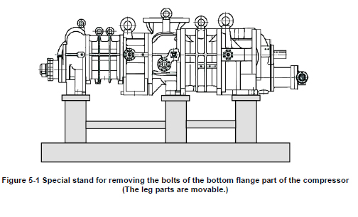
5.3.6 Draining Oil from the Compressor
If three oil drain ports are sealed by flanges without any oil drain pipes, before lifting up the compressor from the base frame or at the stage of placing the compressor on the special stand as shown in Figure 5-1, remove the flanges and drain the oil in the compressor. Prepare oil pans and draining oil containers to receive the large amount of oil flow out. The most part of the oil will be drained from these oil drain ports. The remaining oil will be drained as appropriate in the disassembly process on the surface plate work bench.
5.4 Disassembly and Inspection
During the overhaul work, be very careful in handling the parts. As the compressor is a delicate machine that is operated at very high speed, a minor handling error could result in a situation where the rotor and other major components must be entirely replaced. Another possibility is that it may cause a failure or performance degradation when the compressor is operated after the reassembly. Please fully understand the following sections before starting the work. In general, the disassembly sequence will follow the flow shown on the left side of Figure 5-2 "Illustration of the Disassembly Sequence". Note that the sequence shown is an example, and it may change depending on the situation. For example, it is allowed to separate the low-stage and high-stage blocks at first, as shown on the right side of the flow. Also, in the case of the flow on the left side, the sequence of disassembly may be reversed between the unloader cover/unloader cylinder block and the mechanical seal block.
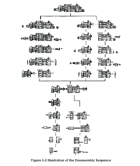
5.4.1 Unloader Indicator
On the 4032**C model, unloader indicators are installed on both the high and low-stages. The high-stage unloader has the same indicator as that for the UD-series single-stage compressors (standard model), while the dial and the micro-switch cam are designed for indicated load of 30 to 100 %. On the low-stage side to be easy to see the indicator dial, the standard indicator assembly is attached with a fixture for 4032**C model that bends the indicator by 90° clockwise or counterclockwise viewed from either of the rotor shaft ends. In the C-series compressor models, 2520**C and 4032**C are made in this structure using "Unloader indicator fixture assembly" and "Standard type unloader indicator assembly" as a low-stage unloader indicator. The unloader indicator assembly has a potentiometer, two micro switches, a micro switch cam, a set of retainers, micro-switch mooting plate, indicator pointer with dial and terminal block.
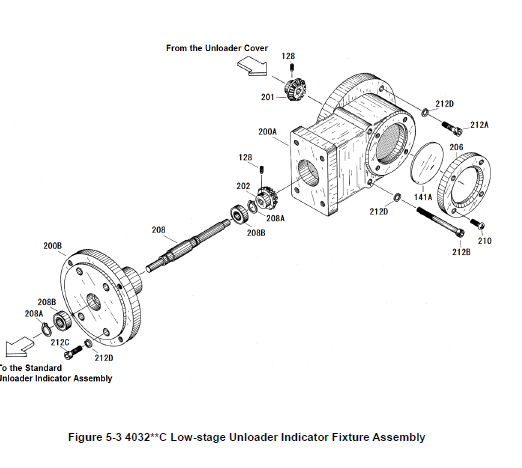
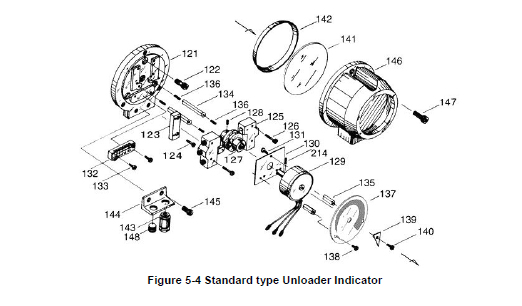
5.4.1.1 Disassembly
■ In Case of Removing the Wiring only
When removing the wiring of the unloader indicator upon removing the compressor, it is necessary to remove the cover as the indicator has a terminal block for the wiring. Perform the work according to the following procedure, and after removing the wires, attach the cover to them for protection. The structure of an unloader indicator assembly is the same as both low-stage and high-stage.
a) By removing the three hexagon socket head cap screws [147] that are used to fasten the indicator cover [146], the cover can be removed.
b) The indicator cover will be removed with the glass [141] and spacer [142] attached. While the glass and spacer are glued, be careful not to drop these as they may be separated from the cover.
c) Remove the plastic plate on the terminal block, and then remove the wiring. Apply vinyl insulation tape to the wiring terminals, and paint identification numbers to prevent them from being mixed up at recovery.
■ When removing unloader indicator assembly parts, with the wiring left as it is
Steps a) and b) are the same as described above.
c) Loosen the cam set screw [128] which secures the micro-switch cam [127] on the shaft of the indicator cam [77-2] on the high-stage side, or on the shaft of the indicator bar [208] of the indicator fixture on the low-stage side.
d) Loosen and remove the hexagon socket head cap screws [122] fastening the micro switch mounting plate [121] to the unloader cover [74-2] on the high-stage side, or to the indicator fixture on the low-stage side.
e) Now, the assembly can be pulled out as it is in the axial direction.
5.4.1.2 Inspection
The inspection procedure is described in the "Reassembly" section of this chapter, as it is often the case that the unloader indicator block is removed as an assembly and later inspected and adjusted after the overhauled compressor is reassembled and installed on the mounting base. Refer to Section 5.5.15 "Unloader Indicator" for details.
5.4.2 Unloader Cover
The unloader cover [74-1] [74-2] is mounted with the indicator cam [77-1] [77-2], which converts the linear motion of the unloader slide valve to a rotational motion, and their mounting parts.
The indicator cam is supported by the ball bearing [78-1] [78-2] and fixed to the cover with a bearing gland [80-1] [80-2]. To make it airtight, the V-ring [82-1] [82-2], spring [83-1] [83-2], and spring retainer [84-1] [84-2] are also attached. The indicator cam has a spiral groove of 340° to cover the moving range of the unloader slide valve. The indicator cam shaft is rotated being pushed by the guide pin [68-1] [68-2] on the top end of the unloader push rod [67-1] [67-2]. This block structure of the low-stage and the high-stage is the same, but there is only one different point that the low-stage hexagon socket head cap screw [81-1] which fastens the bearing gland [80-1] requires the spring washer [597].
5.4.2.1 Disassembly
a) Unscrew and remove the unloader cover mounting hexagon socket head cap screws [76-1] [76-2].
b) Pull the unloader cover with the indicator cam assembly out in the direction parallel to the axis of the push rod in the unloader cylinder. Carefully pull it straight, because if the unloader cover is pulled sideways, the shaft of the indicator cam may be bent.
● The mass of unloader cover assembly is approximately 16kg for the high-stage and approximately 20kg for the low-stage. Because the indicator cam is long, firmly hold the unloader cover assembly until it is completely pulled out from the unloader push rod. Carelessly handling the unloader cover assembly may cause the injury.
c) If the indicator cam will not move normally, check the spiral groove of the indicator cam, ball bearing , and guide pin. The disassembly sequence is as follows: c-1) As the bearing gland [80-1] [80-2], which fixes the indicator cam in place, is secured by three hexagon socket head cap screws [81-1] [81-2] on the cylinder side of the unloader cover, unscrew and remove these bolts. c-2) Then, the indicator cam can be pulled out with the ball bearing [78-1] [78-2] and the snap ring (retaining ring) [79-1] [79-2] attached to the shaft. c-3) Inside the unloader cover, the spring retainer [84-1] [84-2], spring [83-1] [83-2], and then V-ring [82-1] [82-2] are assembled in this order. Because the V-ring is tightly engaged with the bore of the unloader cover, the lip of the V-ring will be damaged when it is once removed, making it unusable again. Therefore, be sure to replace it with a new one once it is disassembled.
5.4.2.2 Inspection
a) Check the packing of the indicator cam shaft for any flaw. If the refrigerant leaks without any flaw observed in this part, it should be due to a defect of the V-ring or installing the V-ring without sufficient oil. In this case, replace the V-ring.
b) Check the spiral groove of the indicator cam. If an abnormal flaw or wear is observed, replace it with a new one.
5.4.3 Unloader Piston and Unloader Cylinder
Inside the unloader cylinder [60-1] [60-2] is an unloader piston [64-1] [64-2] around which the cap seal [66-1] [66-2] and O-ring [65-1] [65-2] are fitted. The unloader piston is assembled to the unloader push rod [67-1] [67-2], which operates the unloader slide valve, with the lock nut [69-1] [69-2]. Note that the low-stage lock nut [69-1] has a double nut arrangement, and that in the high-stage unloader cylinder 30 % (indicated load) unloader spacer is installed to prevent an abnormally high intermediate pressure at the time of compressor start-up.
5.4.3.1 Disassembly
a) Screw two M8 eyebolts in the thread holes of the unloader piston, and pull the unloader piston [64-1] [64-2] fully towards you.
b) Since the low-stage lock nut [69-1] fixing the unloader piston on the unloader push rod has a double nut arrangement, loosen and remove the front side nut by using a lock nut wrench.
c) Then, release the locking teeth of the lock washer [70-1] [70-2], such that the lock nut [69-1] [69-2] can be turned. Then, loosen the lock nut using a lock nut wrench, and remove it.
d) Pull out the unloader piston using the M8 eye bolts again.
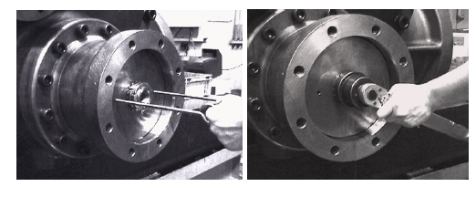
e) The low-stage unloader cylinder [60-1] is fastened by twelve hexagon socket head cap screws [594] to the low-stage bearing cover [16]. Even when all the hexagon socket head cap screws are removed, the unloader cylinder will not drop off as it is securely engaged with the bearing cover. Pull out the unloader cylinder by holding the flange or rib. There are some differences in the mass of unloader cylinder according to the rotor lengths of each model, however each unloader cylinder weighs around 60 kg. Therefore, wind a sling belt on the cylinder as shown in the right picture and remove the cylinder using a crane or like lifting tools.
● In the case of M, L or LL in rotor size, when lifting and pulling out the unloader cylinder completely by keeping the belt sling position as shown in the above picture, the cylinder may hit on the push rod due to the mass unbalance and tilt. When required, change the belt sling position and remove the unloader cylinder.
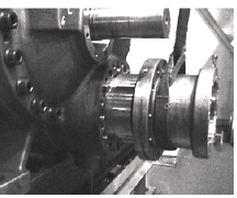
f) The high-stage unloader cylinder [60-2] is fastened to balance piston cover by two shortly hexagon socket head cap screws [61] and fastened to suction cover with balance piston cover by six
long hexagon head cap screws [62]. The high-stage unloader cylinder is to be pulled out similarly to Step e) for the case of low-stage cylinder. However, if the cylinder is to be further disassembled, leave the two bolts [61] fastened. Remove eleven bolts [24] and six bolts [62] fastening the balance piston cover [22], and remove the unloader cylinder together with the balance piston cover. In this, as oil remains in the balance piston and side bearing part, be careful of the oil that will come out when the balance piston cover is removed. If the gasket [23] is sticking and it does not come off, screw in two M8 eye bolts to the two jucking screw threads on the balance piston cover to separate the gasket.
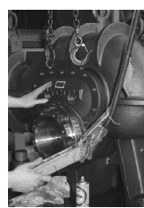
● In case of removing the high-stage unloader cylinder together with the balance piston cover, depending on the model, their mass may weigh over than low-stage unloader cylinder alone.
When removing the high-stage unloader cylinder with balance piston cover, make sure to screw toe eyebolts onto the upper part of the balance piston cover to use a crane or like lifting tools .
5.4.3.2 Inspection
a) Both the O-ring [65-1] [65-2] and cap seal [64-1] [64-2] that are on the periphery of the unloader piston [64-1] [64-2] must be replaced by new ones.
b) As it is often seen that the inside of the unloader cylinder has flaws or is contaminated by oil residue, thoroughly clean the area and use fine sandpapers to finish the surface.
5.4.4 Shaft Seal Block
4032**C models use the double balanced mechanical seal assembly as the shaft seal. According to the system applications and working fluids ( refrigerants), 4032**C applies an appropriate one from appropriate three types of mechanical seal assemblies, i.e., BOD (balanced, O-ring, double) type, BBD (balanced, bellows, double) type, and BBDE (balanced, bellows, double, E* made) type. These mechanical seals are compatible to each other. For disassembly and assembly work of these mechanical seals, a qualified trained personnel and special tools are required. For details, contact us.
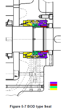
5.4.4.1 Disassembly
After removing the hexagon socket head cap screws [53] and seal cover [51], disassemble in the order of the colored number shown in Figure 5-7/5-8/5-9.
5.4.4.2 Inspection
Although it is instructed that the mechanical seal assembly must be replaced after abnormality is found in the inspection, only visually checking the sliding surface may be insufficient in determining any abnormality. It is thus recommended to always replace it with a new one, similarly to the case of O-rings and gaskets, if the inspection is done in such a way.
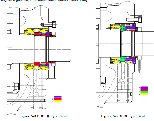
5.4.5 Bearing Cover
The bearing cover [16] must be removed when the low-stage bearing block is inspected or the rotor is pulled out for inspection.
5.4.5.1 Disassembly
a) Before starting the work, protect the rotor axis with curing tapes and/or other protective covering not to damage them.
b) Unscrew and remove 22 in all the hexagon socket head cap screws with captive washer [18-1].
c) Instead of removed bolts, screw in two stud bolts (as shown white arrows in following picture) to top two thread holes on the bearing head for safety.
d) Screw two eyebolts into the thread holes on the upper bearing cover, and keep lifting using lifting tools and a crane or like tools.
e) From the back facing holes on the bearing cover flange surface removed the unloader cylinder, unscrew and remove ten hexagon head cap screws [595A] and two screws [595B] that fasten the bearing cover to the bearing head [11-1]. Even if remove all fastening bolts, the bearing cover is attached to the bearing head by two alignment pins [19-1].
f) There are two jacking screw holes in the opposite positions of the bearing head. By screwing in two left and right M8 eye bolts evenly, the bearing cover will be separated from the bearing head. When some gap is observed between them, use a thin scraper to remove one side of the gasket [17-1] from the body.
g) Further screwing in the eye bolts will disengage the bearing cover from the alignment pins.
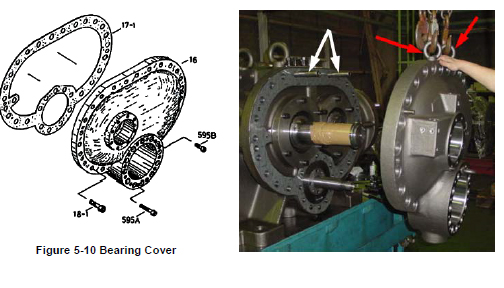
5.4.6 Separating High-stage and Low-stage Blocks
The high-stage and low-stage blocks must be separated before inspecting the gear coupling, high-stage thrust bearing, main bearing, pulled out rotor, etc. As explained at the beginning of Section 5.5 of this chapter, the separation may be done at the initial stage of the overhaul work.
5.4.6.1 Disassembly
a) As it is explained in the Section 5.3.5 , the bolts on the bottom side must be removed by placing the compressor on a special stand before starting the disassembly work.
b) Remove the hexagon socket head cap screws [18-2] that fasten the high-stage bearing head [11-2] to the low-stage suction cover [5-1].
c) As the gasket [17-2] is sticking to both surfaces of the high-stage bearing head and the low-stage suction cover, use the bolts [18-2] that have been removed to screw them into the jacking threads in the bearing head to evenly push the suction cover to separate the two blocks.
d) The gear coupling assembly [151 to 161] for power transmission is located inside, on the side of the M rotor shaft. As the drive side and driven side of the coupling can be separated along the shaft axis, move the main body exactly along the shaft axis to separate them.
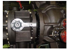
5.4.7 Gear Coupling
The gear coupling, which is used as a power transmission means, is divided into the high-stage side and the low-stage side blocks, with each block attached to the corresponding M rotor shaft, and these two blocks are directly connected by a drive sleeve.
5.4.7.1 Disassembly
a) The drive sleeve [151] can be removed by hand after the high-stage and low-stage are separated.
b) Both high-stage and low-stage, remove the snap ring [18-2] [18-1] that fix the drive hubs [152] using a external snap ring pliers.
c) Both high-stage and low-stage, loosen and remove the knurled cup point socket set screws [159] from the drive hubs used for locking keys [157]. This set screw [159] has been redesigned to the M10×16 with looseness preventing from the M10 ×25 in January 2005.
d) Both high-stage and low-stage, there are two screw holes in the drive hub. Screw M8 eye bolts into these screw holes and pull out the drive hub. It can be easily pulled out, as clearance fit is used.
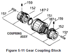
5.4.7.2 Inspection
Check the hub and sleeve for possible deformation of the gear teeth and wear on each tooth flank. If it is found abnormal, replace the whole gear coupling assembly. At the same time, investigate the cause of the abnormality.
5.4.8 Balance Piston
During the operation of a screw compressor, both the rotation rate and the thrust load of the M rotor are higher than those of the F rotor. Accordingly, the service life of the thrust bearing for the M rotor will be significantly shorter than that of the F rotor, if no special measures are taken. As such, in order to reduce the thrust bearing load on the M rotor side, a hydraulic piston is used on the shaft end of the rotor drive shaft to cancel the load.
◆ Note that no balance piston is used on the low-stage. Because the low-stage pressure condition is lower than high-stage, the service life difference of the bearings is not so significant compared to the high-stage.
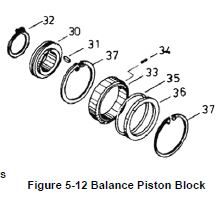
5.4.8.1 Disassembly
a) Remove the snap ring [32] retaining the balance piston [30] on the shaft using external snap ring pliers.
b) Pull the balance piston straight out by screwing two eye bolts into the threaded holes. While the rotor shaft has a balance piston key [31], it is unnecessary to
remove the key. In addition, to prevent rotation of the balance piston sleeve [33], spring pin [34] is used in this models, it is unnecessary to remove the pin.
c) Remove the snap ring [37] securing the balance piston sleeve using the internal snap ring pliers. As the snap ring is pressed out by the internal O-ring [35], slightly pushing it can easily remove the snap ring.
d) Remove the balance piston sleeve and O-ring. As clearance fit is used to engage the outside of the sleeve with the suction cover, you can easily pull it out. As there is an O-ring spacer [36], also remove the spacer.
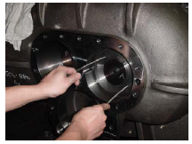
5.4.8.2 Inspection
While you will be able to find some trace of wear on the inside surface of the balance piston sleeve, such wear is not abnormal as it is caused because the clearance between the balance piston and the sleeve is narrower than the clearance between the rotor shaft and the bearing. Because enough clearance is given to the outside of balance piston sleeve in order not to apply the bearing load to the balance piston, no further development of the wear is expected. However, you should still carefully check the condition because when the side bearing is significantly worn, the balance piston may also be worn.
5.4.9 Low-stage Suction Cover and Side Bearings
If the work sequence is such that the thrust bearing block is disassembled first and then the suction cover is removed, there is a risk that, when the suction cover is separated from the main rotor casing, the rotor may also be pull out and dropped. As such, in the procedure described in this manual, the suction cover is removed first, and then the thrust bearing is disassembled.
In this procedure to remove the suction cover before disassembling the thrust bearing block, it is necessary to sufficiently loosen the lock nut that are securing the thrust bearing while the rotor is supported by both the main and side bearings, in order not to d amage the rotor during the disassembly process.
5.4.9.1 Disassembly
a) Screw in two eye bolts to the threaded holes on upper part of low-stage thrust bearing glands [43-1A] [43-1B], then hook and lift them using crane or like lifting tools.
b) Remove the hexagon head bolts [45-1] with spring washers [46-1] fastening the thrust bearing gland [43-1], and then remove the O-ring [150-1] and thrust bearing gland.
The thrust bearing gland may not be removed by pulling only your hands due to the O-ring [150-1] stuck with the thrust bearing gland. In such a case, insert a flat blade screw driver or the like to the gap between the thrust bearing gland and the bearing head, and slightly pull it toward you. The thrust bearing will come off.
c) Unbend the tooth of the lock washers [40-1], and loosen the lock nuts [39-1] on both M rotor side and F rotor side using a lock nut wrench.
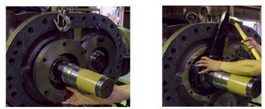
d) Hook up the eyebolts of the low-stage suction cover to the lifting tools of a crane or the like, and then loosen and remove the hexagon socket head cap screws [2-1] securing the suction cover [5-1] to the low-stage main rotor casing [1-1].
e) Drive in the alignment pins [3-1] to the main rotor casing side. If it is not feasible, screw in suitable bolts to the jacking screw holes on the flange to push the suction cover evenly.
f) At this time, the alignment pins will also be disengaged. Even after the alignment pins are disengaged, as the rotor shaft and side bearing are still engaged together, pull out the suction cover carefully along the shaft axis.
g) The side bearing [28-1] has been press fit from the balance piston cover side of the suction cover. Remove the snap ring [29-1] holding the side bearing using internal snap ring pliers.
h) Either push out the side bearing from the main rotor casing side using some block or pull it out using a special tool. For the details of the special tool, refer to Section 5.5.2 in this manual.
5.4.9.2 Inspection
a) Check the oil inlet path to the balance piston part of the suction cover by spraying air, or like.
b) We recommend unconditional exchange of the side bearings on the occasion of the compressor overhaul, but for confirmation of the compressor condition and system operating condition, carefully check the sliding part metal surface of the side bearings. If the metal surface is gray or any foreign matter is buried, also carefully check the wear of the rotor shaft.
c) The inside surface of the main rotor casing should have no problems because sufficient clearance is provided. However, if any trace of scraping by the end of the rotor is found, it should be determined that the thrust bearing is defective. It is also necessary to check the operational condition, such as whether the system is operated for a long time with a high intermediate pressure.
5.410 High-stage Suction Cover and Side Bearings
Similarly to the case of the low-stage side, the lock nut fastening the thrust bearing must be loosened before removing the suction cover.
5.4.10.1 Disassembly
a) Remove the hexagon head bolts [45-2] and the conical spring washers [46-2] that are used to fasten the thrust bearing gland [43-2]. Take care not to lose them.
b) Similarly to the case of the low-stage, it is not easy to remove the thrust bearing gland due to the O-ring [150-2]. Take care not to drop the thrust bearing gland because it weighs 11 kg..
c) Unbend the tooth of the lock washer [40-2] securing the thrust bearing on the rotor shaft, and loosen the lock nut.
d) As the height of the high-stage main rotor casing is low, the casing is installed like a bridge to connect between the suction cover and the bearing head. As such, the main rotor casing will be supported only by one side (i.e., overhang) when the suction cover is removed. To avoid this, either place squared timbers or use a lifting device to properly support the main rotor casing. Moreover, hook up the eyebolts of the high-stage suction cover to the lifting tools of a crane or the like.
e) Loosen and remove the hexagon socket head cap screws [2-2] securing the high-stage suction cover [5-2] to the high-stage main rotor casing [1-2].
f) As the gasket [6-2] of the suction cover is sticking to the surface of the flange, screw two hexagon socket head cap screws [2-2] that have been removed into the screw holes in the main rotor casing flange to evenly push the suction cover. When some gap is observed between them, use a scraper to remove one side of the gasket from the surface.
g) When it comes to the position the alignment pins are disengaged, pull out the suction cover at once along the shaft axis.
h) Remove the snap ring [29-2] holding the side bearing using internal snap ring pliers.
i) Either push out the side bearing from the main rotor casing side using some block or pull it out using a special tool. For the details of the special tool, refer to Section 5.5.2 in this manual..
j) As the high-stage suction cover is installed with an O-ring [328] and O-ring gland [326-2] in the opening for the push rod to pass through, remove them. As the four bolts fastening the O-ring gland are small (M5), be careful not to lose them.
5.4.10.2 Inspection
The inspection must be performed similarly to the case of the low-stage side.
5.4.11 Thrust Bearing Block
5.4.11.1 Disassembly of the High-stage Thrust Bearing Block
For the high-stage thrust bearing, one of two types of bearings, i.e. the ball bearing and the tilting pad thrust bearing, is used according to the working fluid, requirements of the use of the package unit and the applicable standard. This section describes the ball bearing specifications. The specifications of two type bearings are not compatible due to the machining difference
of the bearing head. In case of the tilting pad thrust bearing specifications on the high-stage thrust bearing block, refer to next Section "Disassembly of the Low-stage Thrust Bearing Block".
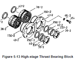
The high-stage thrust bearing block of 4032**C has no spacer for the thrust bearing outer race. While the thrust bearing outer race spacer is used to support (i.e., ensure a sufficient support width for) the outer race of the thrust bearing, 250 or higher models use no spacer for the thrust bearing outer race because the case (bearing head) side has sufficient margin to the support it.
a) Remove the lock nut [39-2] that has been loosened. Then, remove the torsional slip washer [237-2], lock washer [40-2], and thrust washer [250-2].
b) The clearance fit is applied to two gaps between the outer race of the thrust bearing and the bearing head, between the inner race of the thrust bearing and the rotor shaft. Prepare a 1 or 2 mm diameter aluminum wire, make the tip of the wire flat by hammering, and slightly bend the tip to make a hook. Then, insert the tip of the wire between the outer race and the ball retainer of the thrust bearing [38-2] to hook and pull out the bearing. In this way, the bearing can be easily removed.
c) The whole thrust bearing will be removed helped by the surface tension of the oil on the side face. If you have failed to remove the whole bearing at once, put the components in the order of the removal.
d) Inside the thrust bearing is an alignment spacer [42-2] for the inner race on the rotor shaft side. The M rotor side has a marking of "M", and the F rotor side has a marking of "F". Neatly arrange the parts removed, i.e., the thrust bearing gland, thrust washer, thrust bearing, and thrust bearing alignment spacer, separately for the M rotor and F rotor as shown in the right picture. You must be very careful because if an assembly error is made to result in a wrong combination of parts after failing to neatly arranging and separating the parts, it can lead to performance degradation and/or dragging accident due to overheating caused by being too narrow clearance, for example.
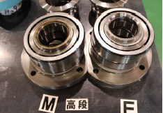
5 .4.11.2 Disassembly of the Low-stage Thrust Bearing Block
a) Remove the lock nut [39-1] that has been loosened. Then, remove the torsional slip washer [237-1], lock washer [40-1], and thrust washer [250-1].
b) Remove the key [346] for TPTB (Tilting Pad Thrust Bearing) on the rotor shaft. This key is easy to lose because it is small. Take care not to lose.
c) Screw two eyebolts into the TPTB and pull it out straight along the rotor shaft until the screw hole for eyebolt comes out (following picture to the left).
d) Attach the lifting eyebolt on the top of the TPTB and pull out it along the rotor shaft using a lifting device (picture in the middle below).
e) Remove the thrust bearing alignment spacer [42-1] (following picture to the right).
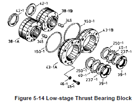
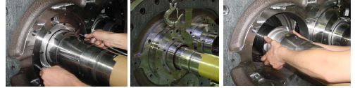
5.4.11.3 Inspection
High-stage Ball Bearing
a) The thrust bearing is normal if the bearing balls are found fully glossy after the thrust bearing has been fully washed and cleaned. It is abnormal if the ball surface has tarnish or streaky pattern.
b) Support the inner race with your hand and rotate the outer race. If you feel abnormal vibration on the hand, the rolling contact surface of the inner or outer race or some balls may be in an abnormal condition. So, carefully check the conditions. You could feel some irregular click even with a small f foreign matter that has entered during the removal process. In such a case, it should return to the normal condition when high pressure air is used to blow out the foreign matters after washing and cleaning the unit. If the bearing is determined to be defective, it must be replaced with new ones.
c) If the inner race and outer race can be easily separated, the wear is considered excessive. If so, you cannot reuse the bearing.
d) After washing the bearing, you should be able to hear a clattering sound when the bearing is rotated by hand. Such a sound is due to the motion of the ball within the backlash or play, or the gap between the retainer and the ball. Such a sound will not be heard if the bearing is held horizontal and turned. If some lubricating oil is applied after washing the bearing, the sound should not be heard when the bearing is turned. If you can still hear the sound, the bearing is abnormal.
e) If any abnormality is seen in the thrust bearing in the above inspection, replace with new ones. In addition, carefully check the reason whether due to mere aging or any problem with the
operating condition and/or lubricating mechanism. If the compressor has been operated for more than 20000 hours without replacing the thrust bearing, it is recommended to replace the bearing with a new one for safely continuing the operation until the next overhaul, even if no abnormality is found in the above described inspection.
Low-stage TPTB (Tilting Pad Thrust Bearing)
a) Disassemble the TPTB and visually inspect the surfaces of the tilting pad and the thrust collar. If any flaw and/or abrasion is found in each tilting pad piece, it is necessary to replace the TPTB
assembly with a new one. If a flaw of the thrust collar is small, finish with sandpaper.
b) Perform visually inspection of the sliding surface of the floating seal and the thrust collar. If each flaw is small, wash and finish it with sandpaper.
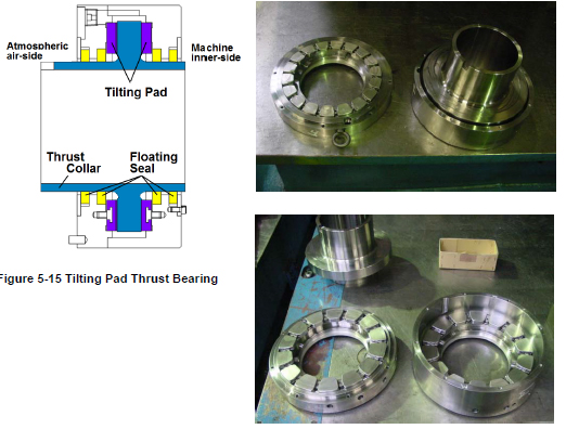
5.4.12 Rotors and Main rotor casing (Low-stage/High-stage)
5.4.12.1 Disassembly
a) While you can pull out the rotor either from the M or F side, you should be very careful in the work as both of rotors are very heavy. In particular, be careful not to flaw the Low-stage M rotor shaft because the shaft area is installed the mechanical seal assembly. We recommend you to protect the shaft portion using curing tapes beforehand. When pulling out the M rotor (or F rotor) first, pull out about 2/3 of the full length of the rotor by holding the shaft upward a little and turning it in the CW (or CCW) direction.
b) As a preparation, use a nylon belt or other lifting belt that will not blemish the lifting surface to support the center of the rotor. Then, pull out the rotor while slightly lifting up the rotor using the belt.
c) The pulled out rotor should not be directly placed on the floor. Use appropriate wood boards to support the rotor as a cushion to prevent blemishing or use V-blocks to support the shaft to prevent blemishing of the outer surface (See right picture.)
5.4.12.2 Inspection
a) No abnormality should be observed on the surface of the rotor lobes under normal operations. Regarding the contact surface of the lobes black luster should be seen on the root area of the M rotor lobes and on the tip area of the F rotor lobes. In other cases, when the suction gas or oil is contaminated by fine dust, there may be fine linear scratches on the shaft surface, in the direction perpendicular to the shaft axis. If any such flaw is found, use a fine sandpaper or grindstone to smooth the surface.
b) In case of ammonia refrigerant or gas compressor, the non-contact surface of the rotor may be discolored by rust or deposits. Use sandpapers or others to finish the surface according to the degree of the problem.
c) Then, check the bearing areas of the rotor shaft. Two types of finishing are used: one is the induction hardening (polish finishing) for the standard specification, and the other is the hard chrome plating (polish finishing), as a special specification. The most suitable finish is selected according to the type of refrigerant and operation conditions. Very little wear will be present unless the compressor is operated for a long time using dirty oil or any hard matter is buried in the metal of the inner circumference of the bearing.
d) Check the portion of the shaft on which the thrust bearing is mounted for any trace to show that the inner race of the bearing has rotated. f the lock nut that fastens the inner race of the thrust bearing is loosened, or if the bearing is abnormally worn, the inner race will become rotate. If any trace of rotation is seen, correct the problem. Depending on the degree of the rotating trace, it might be necessary to replace the rotors with new ones.
e) Check the inner surface of the main rotor casing. There is a narrow clearance between the periphery of the rotor and the main rotor casing. Any slight flaw present on the tip of the rotor lobes or on the inner surface of the main rotor casing, due to small foreign matters, will not be a problem. If there is any trace to show that the tips of the rotor lobes have hit the inner surface of the main rotor casing, it is an abnormal condition. In such a case, the possible cause is that the main bearing and/or side bearing is worn out. Take proper actions by finding the cause of the problem, such as contamination of the lubricating oil or entrance of foreign matters.
5.4.13 High-stage Bearing Head and Main Bearings
On the rotor mounting side of the bearing head [11-2], there is a gas discharge port as determined by the operating conditions of the compressor. This discharge port affects the performance of the compressor. In addition, the bearing head has the main bearing that supports one end of the rotor.
5.4.13.1 Disassembly
a) Remove all the hexagon socket head cap screws [2-2] fastening the main rotor casing and the bearing head. Support the foot of the main rotor casing using squared timbers.
b) Use jacking bolts to evenly push the bearing head. Once some gap is produced between the main rotor casing and the bearing head, use a scraper to detach the gasket from the bearing head and put it on to the main rotor casing side. When the alignment pins are disengaged, the bearing head is separated from the main rotor casing.
c) The main bearing [27-2] is lightly press fit into the bearing head. When removing the main bearing, first use internal snap ring priers to remove the snap ring [29-2]. Then, either use a plastic block or other suitable element to push the main bearing from the rotor side or use a special tool to pull out the main bearing. For the details of the special tool, refer to Section 5.5.2 in this manual.
d) The unloader slide valve can be removed as an assembly by pulling it out from the bearing head side. If no specific abnormality is found, no further disassembly is required.
e) The guide block stem [88-2] is screwed in from the bottom of the main rotor casing, and the guide block [87-2] is engaged from the top. To replace the O-rings [89-2], remove the guide block stem.
5.4.13.2 Inspection
a) We recommend as well as the side bearings, unconditional exchange of the main bearings on the occasion of the compressor overhaul, but for confirmation of the compressor condition and system operating condition, carefully check the sliding part metal surface of the main bearings. If the metal surface is gray or any foreign matter is buried, also carefully check the wear of the rotor shaft.
b) Check the condition of the surface of the bearing head on the rotor side, where the discharge port is. Properly mend the surface if any flaw is observed. If the entire surface has significant flaws, either the thrust bearing is defective or the end clearance adjustment is poor. If oil compression has been caused during the operation, carefully and thoroughly check the area of the discharge port in particular. If the continued use is in doubt at all, perform the penetrant testing to determine if it can be used or not.
c) With the unloader slide valve mounted in position, check the step height between the slide valve and the main rotor casing surfaces. Usually, the surface of the slide valve should be lower than the surface of the main rotor casing. If the top surface of the slide valve has a trace of hitting the rotor, the probable cause is that the slide valve is worn or the rotor shaft/bearing is worn. In this case, please contact our sales offices or service centers.
d) Check the properness of the guide pin [68-2] at the tip of the unloader push rod [67-2] that engages with the indicator cam [77-2].
5.4.14 Low-stage Bearing Head and Main Bearings
5.4.14.1 Disassembly
a) Unscrew and remove all the hexagon socket head cap screws [2-1].
b) Drive in the alignment pins [3-1] from the bearing head side to the main rotor casing side.
c) Screw tow jacking bolts into screw holes on the flange portion of the main rotor casing, then screw the bolts evenly to push and separate the bearing head and the main rotor casing.
d) Separate them carefully along the shaft axis, as the unloader push rod [67-1] is engaged.
e) The main bearing [27-1] can be easily pulled out by removing the snap ring [29-1] and then lightly tapping it from the rotor side via a pad. Otherwise, use a special tool to pull it out.
f) Remove the slide valve as an assembly, using the same procedure as for the high-stage unit. Carefully perform the work using lifting tools, as you are handling a heavy object.
5.4.14.2 Inspection
The inspection must be performed similarly to the case of the high-stage side.
5.5 Reassembly
During the reassembly work, be very careful in selecting the correct replacement O-rings of the specified standard, not to make a mistake regarding the size, material, for fixed use, for sliding use, etc. Using a wrong O-ring can lead to oil leak or other problems.
Some gaskets are not symmetrically shaped. In such a case, be careful not to misplace the gasket. If the gasket is misplaced, it can lead to a significant problem such as blocking any oil supply route on the casing.
After completing the disassembly and inspection procedures, start the assembly process. Fist, read Section 5.1 "Precautions for Maintenance and Inspection" again in this Chapter 5. Before starting the assembly, check the replacement parts once again. Like gaskets, all O-rings that have been removed during the compressor disassembly must be replaced with new ones.
The assembly sequence is mostly the reverse of the disassembly sequence. First of all, clean the work bench and the tools to be used.
Immediately prior to the assembly, use washing agent (e.g., kerosene, parts cleaner) to clean the parts to be assembled, dry them with compressed air, and sufficiently apply lubricating oil, etc. For this, prepare a sufficient amount of clean lubricating oil for the reassembly. Also, apply oil on both sides of the gasket.
Because the assembly procedure is mostly similar between the high-stage and low-stage, the following Sections provide explanations that are commonly used for both stages. For this purpose, the part number given in the common explanations will omit the distinction between high-stage and low-stage by means of a hyphenated suffix (the suffix of [**-1] for low-stage and [**-2] for high-stage part number will be omitted).
Please fully understand the details in this Section 5.5 for correct assembly work.

5.5.1 Unloader Slide Valve
a) Attach two O-rings [89] on the guide block stem [88] and screw in the guide block stem securely from the bottom of the main rotor casing [1]. Then, mount the guide block [87] in the casing. In the case of 4032**C models, the guide block is not used in the low-stage main rotor casing.
b) If the slide valve assembly has been disassembled, first make sure that the alignment position between the unloader slide valves [54] and [55] is accurately reproduced and then tighten the
hexagon socket head cap screws [58] with spring washers [267] at the specified torque. The outer diameter of the spring washers used here is less than normal spring washers for hexagon socket head cap screws. So, be careful not to mix up with other washers. In the case of 4032**C models, the unloader slide valve [55] is only used in high-stage side.
c) After using a grind stone or fine sand paper to lightly finish the circumference of the assembly, mount the assembly in the main rotor casing using a crane or like. In the high-stage side, slowly push-in the slide valve while aligning the groove of the slide valve with the guide block.
d) After it is assembled, hold the unloader push rod and move it for several times to check that it moves smoothly. Then, carefully check the joint with the casing that there is no step between them.
◆ A slight step between the surfaces of the unloader slide valve and the casing is allowed if the slide valve side is lower. If the step is such that the surface of the unloader slide valve is higher than the surface of the rotor casing, it is considered the problem of assembly. In such a case, it must not be left uncorrected. Be sure to reassemble it. Otherwise, the periphery of the rotor can make contact with the slide valve, resulting in a severe damage.
e) The low-stage slide valve assembly has a external snap ring [661] not to move the slide valve toward the bearing head exceeding the necessary position (i.e., indicated load 0%). If you remove this snap ring [661] at the time of disassembly,, never forget to attach the snap ring. Without this snap ring, it may occur the incident that the slide valve assembly will not move toward loading direction.
5.5.2 Bearing Head and Main Bearings
The main bearing (O-ring type) [27] is installed by a light press fit. The size of O-ring [432-1] attaching on the low-stage main bearing has been changed to JIS B 2401 G200 from G210 according to the design modification in September 2012.
a) Align the notch on the main bearing with the spring pin [14] that is driven in into the bearing head [11], and then drive it in with a pad. For the alignment, it is convenient to use a tool such as a guide bar (as a red arrow shown in the right picture) .
b) After the bearing has been inserted, install the internal snap ring [29] to retain the bearing in position. Securely install the snap ring to be fully seated in the ring groove, by pushing the snap ring with a guide bar or the like, or by lightly hitting the guide bar with a hammer while placing the guide bar on the snap ring.
When press fitting the bearing, it is recommended to prepare a collared plastic cylinder (spacer) that exactly fits inside the inner diameter of the bearing and also a collared weight that fits inside the plastic cylinder as shown in Figure 5-17. Then, hit the top of the weight for easy press fitting of the bearing.
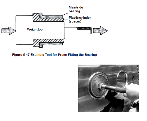
5.5.3 Bearing Head and Rotor Casing
a) After fitting the unloader push rod [67-1] into the hole of the bearing head [11-1], slide either the bearing head or the rotor casing [1] to join them together.
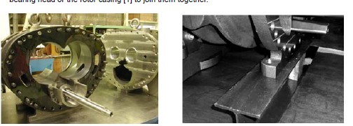
b) As the full height of the high-stage main rotor casing [1-2] is lower than that of the bearing head, both centers will not be aligned when they are placed on the work bench. Therefore, either use a pedestal as used in the disassembly process or lift the main rotor casing using a crane or other device to align the centers.
c) After lightly fastening two bolts, drive in the alignment pins [3] to fix the position by using a copper or an aluminum hammer. Note that a low-stage hexagon socket head cap screw [2-1] is a washer faced bolt.
d) After tightening the bolts [2], check that the bearing head gasket is not protruding into the inside of the main rotor casing.
e) Also, move the slide valve back and forth to check that it works normally.
f) The bottom bolts that cannot be fastened on the work bench are to be fastened later on.

g) Attach the O-ring gland [326-1] on the low-stage bearing head where is the part of the unloader push rod protruding. Attach two O-rings [325] and four backup rings [419] alternately on the two O-ring grooves in the O-ring gland inner circumference.
h) Also attach the O-ring [9] on the O-ring groove of the O-ring gland outer circumference.
i) Then, mount the O-ring gland on the unloader push rod and push it into the bearing head [11-1].
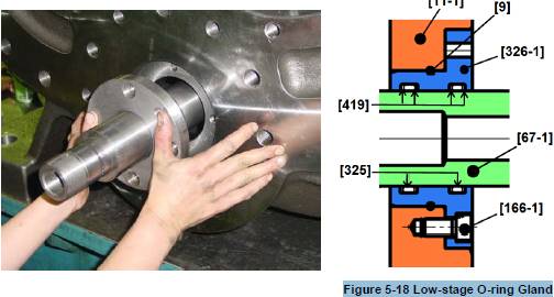
j) Tighten the O-ring gland to the low-stage bearing head using four hexagon head cap screw [166-1].
k) Attach the O-ring [73-1] on the tip of the unloader push rod.
5.5.4 Installing the Rotors
The rotor must be sufficiently reworked. If any slight flaw is observed on the shaft surface in the area of attaching the bearing and mechanical seal assembly, use a sand paper to correct and finish the surface. After finishing the surface to attach the seal, apply protective tape on the surface. Both the M rotor and F rotor have a specific engagement position, and the position is marked by carving. In order to make it easier to match the positions when the rotors are installed into the main rotor casing, a number is marked on the lobe tip: the M rotor has the marking on the discharge side, and the F rotor has the marking on the suction side.
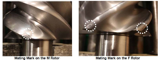
a) Apply sufficient amount of lubricating oil on the main bearing in the bearing head and on the bearing area of the rotor shaft.
b) While it is easier to mate the markings if the F rotor is first installed into the casing, it is not a mistake to install the M rotor first.
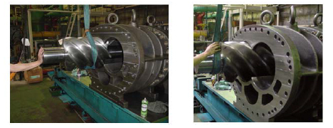
5.5.5 Suction Cover and Side Bearings
Similarly to the main bearing, the side bearing (O-ring type) [28] is machined to the size that will allow light press fitting to the suction cover [5].
In addition as is the case with the O-ring for the main bearing, the size of the O-ring for the low-stage side bearing has been changed to JIS B 2401 G200 from G210 according to the design modification.
a) Press fit the bearing by aligning the notch position of the side bearing with the spring pin [8] for positioning the side bearing driven-in on the suction cover. During the press fitting process, check that the notch position of the bearing is at the pin position. If the position has been shifted, pull out the bearing and try the press fitting process again. Similarly to installing the main bearing, for press fitting the side bearing, it is convenient to use a guide bar and/or a special tool for installing/removing the sleeve type bearing.
b) After the bearing has been installed, install the internal snap ring [29] to retain the side bearing. Make sure that the snap ring is fully seated in the ring groove either by pushing the ring with a guide bar or tapping the head of the guide bar while applying the bar on the snap ring.
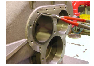
c) Attach the O-ring [328] on stepped processing part of the high-stage suction cover [5-2] hole where the unloader push rod passes. Then, attach the O-ring gland [326-2] on the hole and tighten the O-ring gland to the suction cover using four hexagon socket head cap screws [166-2].
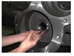
5.5.6 Installing the Suction Cover
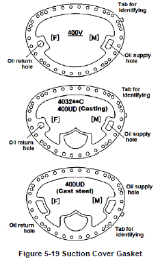
Both of the high-stage and low-stage suction cover gaskets [6] are not symmetrically shaped. Also, as shown in Figure 5-19, there are three type gaskets in the same sizing. Be careful not to use a wrong gasket. After the design modification in June 2008, the tabs have been added on the suction cover gasket for identifying the left/right and the applicable model
a) Apply sufficient oil on both sides of the gasket, confirm the oil supply/return holes position and put the gasket on the main rotor casing.
b) At first on the high-stage, pass the unloader push rod through the hole at the bottom of the suction cover [5-2]. Slide (or use a lifting device to move) the suction cover in parallel along the shaft axis to engage the rotor shafts with the side bearings. At this time, be careful not to damage the inside surface of the side bearing by the shaft end. As the low-stage unloader push rod is out to the bearing head side, be careful only with the rotor shaft end in this work.
c) After the suction cover has been pushed in up to the flange surface, lightly fasten some of the bolts [2].
d) Using a copper hammer or an aluminum hammer, drive in the alignment pins [3].
e) Tighten the hexagon socket head cap screws evenly up to the specified tightening torque. The bolts on the bottom side (about 6 bolts) are to be tightened during the final assembly stage, on the special stand used in the disassembly process.
f) For both the high-stage and low-stage blocks, move the unloader push rod back and force by hand to check that it is working normally.
g) Hold and rotate the M rotor shaft to check if it works normally. In addition, check that the rotor has an axial play (i.e., the rotor can move in the axial direction).
5.5.7 Balance Piston and Balance Piston Sleeve
Install the balance piston sleeve to the high-stage suction cover, and install the balance piston on the M rotor shaft end portion of the high-stage suction cover side. The installation of the balance piston sleeve may be done either before the suction cover installation to the main rotor casing.
a) First install the internal snap ring [37] for the O-ring spacer [36], and then install the spacer [36].
b) After setting the O-ring [35] in position, install the balance piston sleeve [33]. Insert the chamfered side of the balance piston sleeve towards the O-ring already placed. Also, align the notch of the balance piston sleeve to the spring pin [34] for rotation stop and to the oil supply port.
c) Insert the snap ring [37] to retain the balance piston sleeve. As it should be difficult to fit the snap ring into the groove due to the elastic force of the O-ring, either push the side of the ring by a guide bar or tap the head of the guide bar to fit the ring securely into the groove.
d) Confirm the balance piston key [31] attached on the M rotor shaft end of the high-stage suction cover.
e) Push the balance piston [30] into the high-stage suction cover using two eyebolts.
f) Install the snap ring [32] using external snap ring pliers and retain the balance piston. Confirm the snap ring fitted into the groove.
g) Install the O-ring [73-2] on the unloader push rod [67-2].
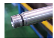
5.5.8 Thrust Bearing Block
Table 5-10 Components of the thrust bearing block
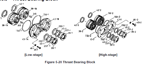
P/N Part Name Q'ty
Low-stage High-stage Low-stage High-stage
42-1 42-2 Thrust bearing alignment spacer (1), (2) 2 2
38-1A 38-2 Thrust bearing (1), M rotor, (2) 1 2
38-1B - Thrust bearing (1), F rotor 1 -
346 - Shaft key for TPTB 2 -
150-1 150-2 O-ring 2 2
43-1A 43-2 Thrust bearing gland (1A), (2) 1 2
43-1B - Thrust bearing gland (1B) 1 -
250-1 250-2 Thrust washer (1), (2) 2 2
40-1 40-2 Lock washer (1), (2) 2 2
237-1 237-2 Torsional slip washer (1), (2) 2 2
39-1 39-2 Lock nut (1), (2) 2 2
46-1 - Spring washer, hexagon socket head cap screw 12 -
- 46-2 Conical spring washer (2) - 8
45-1 - Hexagon socket head cap screw (1) 12 -
- 45-2 Hexagon head bolt (2) - 8
The torsional slip washer [237] and lock washer [39] must be replaced with new ones.
If the removed thrust bearing is to be installed as it is, check the marking of "M" or "F" on the thrust bearing alignment spacer and assemble it in the same combination as it was disassembled. This is important in controlling the end clearance on the discharge side of the rotor.
Even if the same bearing is installed, the work must be very carefully done as the dimension can change if any foreign matter such as a chip of paint or dust is pinched by the alignment spacer.
In determining the installation direction of the thrust bearing, there are two methods depending on the existence of an alignment "V" marking on the outer circumference of the bearing. Install the bearing according to the following procedure provided for each case.
5.5.8.1 High-stage Block
As described in Section 5.4.11, for the high-stage thrust bearings, two types of bearings, i.e. the ball bearing and the tilting pad thrust bearing, is used according to the working fluid, requirements of the use of the package unit and the applicable standard. This section describes the ball bearing specifications.
In the case of the tilting pad thrust bearing specifications on the high-stage thrust bearing block, refer to next Section "Low-stage Block". The thrust bearing alignment spacer [42-2] and the thrust bearing gland [43-2] are different from the ball bearing specifications. The assembly sequence for this part is as illustrated in Figure 5-20. The important points to be noted in the procedure are described below:
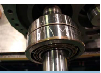
a) Check the marking of either "M" or "F" on the thrust bearing alignment spacer to ensure that the units are assembled in the same combination of parts. The front and back of the thrust bearing alignment spacer must be distinguished when it is installed. The larger chamfering side is on the machine side, and the smaller chamfering side is on the thrust bearing side.
b) If thrust bearing has a "V" marking on the outer circumference, it means that the installation direction of the bearing will sensitively affect the end clearance adjustment. In this case, the bearing must be installed with the pointed end of the marking pointed toward the inside of the machine. If there is no "V" marking, it means that the direction of the bearing installation will not affect the end clearance adjustment. However, in order to clearly determine the orientation (whether it is on the inside or outside of the machine), first combine both bearings with the bearing number carving facing the outside of the machine. Then, use a blue whetstone to write the above "V" marking on the bearing to show the inside direction of the machine. Then, install the bearing (above picture).
c) After the thrust bearing has been installed, attach the thrust washer [250-2], lock washer [40-2], and torsional slip washer [237-2]. Then, tighten the lock nut at the specified range of the tightening angle (refer to Chapter 7, Section 7.3 "Tightening Torques for Bolts and Nuts" in this manual) to secure the inner race of the thrust bearing on the rotor shaft. This specified range of lock nut tightening angle is the same as the ball bearing specifications and the TPTB specifications.
5.5.8.2 Low-stage Block
The TPTB (Tilting Pad Thrust Bearing) is used as the low-stage thrust bearing. The TPTB for M rotor and the TPTB for F rotor are the same in outer diameter and inner diameter, but are different in lengths. The M rotor TPTB is longer than the F rotor TPTB because M rotor thrust load is larger than F rotor thrust load. Check the End Play
Before assembling this block, measure the end play of the TPTB. When putting the TPTB on the flat and smooth top of the work bench, the end face of the thrust collar rises up as shown below left picture. Then, putting the TPTB on a pedestal which has a larger inner diameter hole than a outer diameter of the thrust collar, the thrust collar falls in the pedestal hole as shown below right picture. We call this amount of movement of the thrust collar end face as the end play. If this value (end play) is not within the specified range as shown in Table 5-10, the TPTB can not to be used. Record the measurement value.
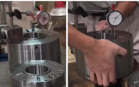
Table 5-10 Specified Value of End Play
Assembly
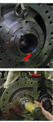
a) Apply protective tape or like on the M rotor axis portion installing the shaft seal beforehand.
b) Confirm the marking M/F of the thrust bearing alignment spacer [42-1], and install them with the same combination when disassembled. There is a specific installing direction of the thrust bearing alignment spacer. The larger chamfering side is on the machine side, and the smaller chamfering side is on the thrust bearing side.
c) Attach a lifting eye bolt on the top of the TPTB in the same manner at the time of disassembling, and install the TPTB while lifting by a crane or like lifting device. Using two eye bolts and pushing with them will make the work easier. At this time, align the detent protrusion of the TPTB (as shown a red arrow in right above picture) beneath.
d) Attach the shaft key [346] for the TPTB.
e) After installing the TPTB, install the thrust washer [250-1], lock washer [40-1], and torsional slip washer [237-1]. Then, tighten the lock nut [39-1] with the specified range of lock nut tightening angle to secure the thrust collar of the TPTB on the rotor shaft.
Note: In case of using the TPTB for the high-stage, align the protrusion of the TPTB just above. In addition, the thrust washer is not installed to the high-stage.
5.5.8.3 End Clearance Measurement
At this point (i.e., after the thrust bearing block has been fully assembled), measure the clearance between the bearing head end face and the rotor end face on the discharge side. This clearance is called as the end clearance. There is no difference between the TPTB and the ball bearing specifications in the manner of end clearance measurement and adjustment. If the measured clearance does not satisfy the range specified in Table 5-11, proper adjustment must be made.
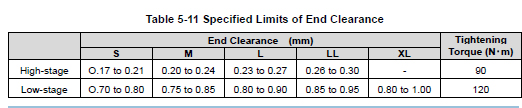
a) Pressing the rotor shaft on to the discharge side with securing the thrust bearing to the rotor shaft. In case of the high-stage, the rotor can be pushed to the discharge side by tapping with cushion like Teflon block, not striking the rotor shaft end directly, but the same method cannot be applied to the low-stage. Manufacturing and preparing a jacking bolt to press the rotor shaft end face from the suction side and its supporting jig (i.e., a steel plate with about 15 mm thickness and threaded hole at the position of the rotor end face, fixing to two opposite positions bolt holes of the suction cover flange) will make this pressing work easier.
b) Prepare the thrust bearing gland to be readily mounted. Mount a dial gauge on the axial end of the rotor, and set the indication needle to zero point while the rotor is fully pressed onto the discharge end face.
c) Without inserting the (conical) spring washer [46] and the O-ring [150], tighten the fastening bolts of the bearing gland sequentially and evenly up to the specified tightening torque. In case of the TPTB, align the notch of the thrust bearing gland to the protrusion of the TPTB. Tightening each bolt at once at the specified torque must be avoided because it will result in uneven tightening. So, repeat to sequentially tighten the bolts for several times.
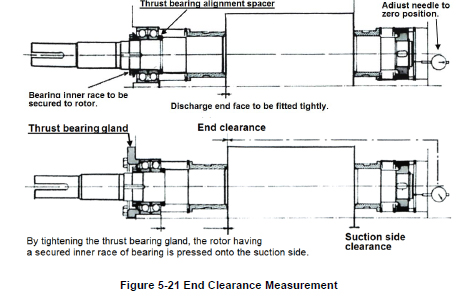
d) Then, read the dial gauge indication. This value shows the actual end clearance. If the end clearance is outside the specified value, perform the adjustment work described in the next section. If the end clearance is within the specified value, turn the M rotor shaft by hand and confirm the smooth turning without uneven tightening. And then perform the measurement of the run-out of the rotor shaft described in next section (3).
5.5.8.4 End Clearance Adjustment Procedure
(1) When the end clearance is less than the specified value In this case, a shim (thrust adjustment liner) must be inserted between the thrust bearing alignment spacer [42] and the inner race of the thrust bearing to increase the end clearance. The thickness of the shim must be determined by the difference between the specified end clearance and the measured value.
◆ Although the thrust adjustment liner is not shown in the development view, you can place an order to us indicating the model name.
(2) When the end clearance exceeds the specified value If any shim (thrust adjustment liner) has been inserted between the thrust bearing alignment spacer and the inner race of the thrust bearing, and the thickness corresponds to the difference between the measured end clearance and the specified value, just remove the shim. If no shim is used or the thickness of the shim is insufficient to compensate for the excess end clearance, use a surface-grinding machine (or ask a vendor) to make the thrust bearing alignment spacer [42] thinner by the amount of the end clearance difference between the measured and specified values. After the surface grinding is done, use a micrometer to measure the thickness of the spacer for the entire circumference to make sure the thickness is uniform.
(3) Measuring the run-out of the rotor shaft (low-stage M rotor) If the end clearance adjustment has been successfully completed, then measure the run-out of the low-stage M rotor shaft using a dial gauge at the point of the mechanical seal attachment and turning the shaft by hand. A run-out of up to 0.03 mm is acceptable for all models. The run-out occurs if the thickness of the thrust bearing alignment spacer is not even or the marking on the thrust bearing is not properly positioned. And it occurs if fastening the lock nut performed without changing the position of the lock nut wrench (i.e., uneven fastening of the lock nut). The run-out also becomes significant if any small foreign matter is present in between relevant parts.
5.5.8.5 Tightening after Finishing the End Clearance Adjustment
a) Remove the thrust bearing glands [43].
b) Bend the tooth of the lock washer [40] to set it in the notched part of the lock nut to prevent loosening.
c) Attach the O-ring [150] to removed thrust bearing gland. Without inserting the (conical) spring washers [46] in the same manner as in the case of the end clearance measurement/alignment,
tighten the hexagon head bolts [45] in a diagonal sequence, a little at a time, and finally tighten them to the specified torque.
d) Remove one of the hexagon head bolts fastening the thrust bearing gland, insert the (conical) spring washer, tighten the bolt at the specified torque, and repeat this procedure for all other
hexagon head bolts.
5.5.9 Balance Piston Cover and High-stage Unloader Cylinder
a) Install the unload spacer [420] attached two O-rings [421] in the inner circumference grooves on the high-stage unloader push rod [67-2]. This unload spacer is used as high-stage load capacity adjustment (minimum 30 % load) to prevent overload of the driving machine at the time of compressor start-up.
b) Install the unloader cylinder [60-2] on the balance piston cover [22] and then install the resulting assembly on the high-stage suction cover [5-2]. However the balance piston cover and the unloader cylinder are often not disassembled, so following procedures c) to f) are applied to the case that this block has disassembled.
c) Attach the O-ring [63-2] in the O-ring groove on the machined surface of the balance piston cover along which the unloader cylinder is installed.
d) Align the position of the balance piston cover with the unloader cylinder. As no gasket is used on the mating flange between the balance piston cover and unloader cylinder, evenly and thinly apply liquid gasket (made of special synthetic rubber) on the surface of the flange of the unloader cylinder inside from the center of the bolt holes.
e) As the O-ring of the balance piston cover is already installed, lightly tap the flange surface with a soft hammer to install it.
f) When joining the flanges, also align the bolt hole positions. Then, insert two hexagon socket head cap screws [61] in the positions near the 10:10 of clock to tighten the unloader cylinder to the balance piston cover.
g) Confirm the O-ring [73-2] is attached in the O-ring groove on the tip of the unloader push rod [67-2], at the position where the unloader piston is installed.
h) Attach the O-ring [65-2] without lubricating oil on the unloader piston [64-2], and then install the cap seal [66-2] on it. It can be smoothly installed by slightly folding the cap seal along the circumferential direction. Also, using a small and smooth spatula will facilitate the assembling work.
i) Install the unloader piston fitted with the O-ring and cap seal in the unloader cylinder. One side of the unloader piston is with screw holes for eye bolts, while the other side does not have such holes. First, to make it easier to fit the cap seal on the unloader cylinder wall, lightly press one side of the piston onto the chamfered area of the unloader cylinder by hand, changing the side of the piston for several times. Finally, apply lubricating oil to the unloader cylinder, then, push and install the piston with the screw holes side of the piston facing the unloader cover. After the installation, check that the cap seal is not broken or pinched.
j) Push the unloader piston into the unloader cylinder and set it in the middle of the cylinder, pull the unloader push rod [67-2] toward you.
k) Apply sufficient amount of oil to the balance piston cover gasket [23] and attach the gasket on the balance piston cover flange surface. Then, lift up the assembly of the balance piston cover and the unloader cylinder using a crane or like lifting device, and install the assembly onto the high-stage suction cover. In the middle, pushing the unloader piston into the push rod and temporarily fastening the lock nut [69-2] in the course of the work will make later work easier.
m) After joining the flanges together, tighten the hexagon socket head cap screws [24] of the balance piston cover and tighten the hexagon socket head cap screws [62-2] of the unloader cylinder at each specified torque.
n) Use the eye bolts to pull the piston toward you, once remove the temporarily fastened lock nut, install the lock washer [70-2] and lock nut [69-2], and then tighten the lock nut at the specified torque. To prevent loosening, bend the tooth of the lock washer at the notch of the lock nut. Lastly, use the eye bolts to check the smooth movement of the piston.
5.5.10 Bearing Cover
a) Before installing the bearing cover [16], check that the teeth of the lock washers of the thrust bearing part have been properly bent to prevent rotation and that the hexagon head bolts fastening the thrust bearing gland are with spring washers.
b) For ensuring the safety, screw two stud bolts in the upper bolt holes on the flange of the low-stage bearing head [11-1].
c) After applying sufficient amount of oil or like on the flange surface of the bearing head as well as on both sides of the bearing cover gasket [17-1], hang the gasket from the upper stud bolts and attach the gasket onto the flange surface of the bearing head.
d) While lifting the bearing cover [16] using a lifting hook on the eye bolt, install the bearing cover carefully not to make contact with the M rotor shaft and/or the push rod.
e) After correctly setting the position of the alignment pins, lightly tap the flange at opposite places alternately using a copper hammer or soft hammer to install the cover in position.
f) When the cover has come to the position the bolts can be screwed in, screw in two or three hexagon socket head cap screws [18-1] and evenly tighten them to reduce the clearance and make the cover contact the body. Then, tighten all the bolts at the specified torque.
g) There are two types of the hexagon socket head cap screws as [595A] and [595B] shown in Figure 5-22. These bolts are used for fastening the countersunk processed screw holes of the bearing cover flange surface installing the unloader cylinder. First, tighten opposite four positions, i. e., up, down, right and left with M24 bolts [595A]. Then, screw two M20 bolts [595B] into thread holes positioned 10:10 of clock, and tighten to the specified torque.
h) Tighten all remaining bolts [18-1] and [595A] at the specified torque.

5.5.11 Shaft Seal Block
The assembly procedure of the shaft seal block is the reverse sequence described in Section 5.4.4 as shown in the order of the colored number of each sectional view drawing. Disassembly and assembly works of this block especially require qualified trained personnel and special tools. For details contact us.
Note that to confirm the sliding surface pressure of the mechanical seal is proper or not, measure the clearance between the surfaces of the seal cover gasket and the bearing cover flange. This clearance is called " fastening margin of the seal", it should be measured by using a taper gauge. The proper value guide line (reference) of this " fastening margin of the seal" is; 3 mm as BOD type seal, 5 mm as BBDⅡ type seal, and 6 mm as BBDE type seal.
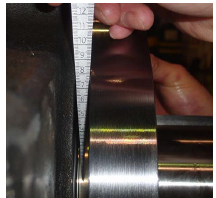
5.5.12 Low-stage Unloader Cylinder
The installation of the low-stage unloader cylinder may be done either after the bearing cover installation described in Section 5.5.10 or after the assembly of the shaft seal block.
a) Check that the O-ring [73-1] is inserted in the O-ring groove on the tip of the unloader push rod [67-1], at the position where the unloader piston is installed.
b) Install the O-ring [65-1] and cap seal [66-1] on the unloader piston [64-1].
c) Install the unloader piston fitted with the O-ring and cap seal in the unloader cylinder [60-1]. The work procedure is the same as that for the high-stage side as described in Section 5.5.9, item i).
d) In case of 4032**C, the O-ring [63-1] for sealing between the bearing cover [16] and the unloader cylinder is installed on the O-ring groove in the unloader cylinder.
e) Install the unloader cylinder into the bearing cover, and fasten the twelve hexagon socket head cap screws [594] evenly at the specified tightening torque.
f) Set the lock washer [70-1] and lock nut [69-1] on the unloader push rod, and fasten the lock nut at the specified torque using a lock nut wrench. To prevent loosening, align the positions of the lock washer’s tooth and the notched part of the lock nut, and bend the lock washer’s tooth. Lastly, use the eye bolts to check the movement of the unloader piston.

5.5.13 Unloader Cover
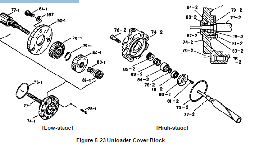
a) Use eye bolts to move the unloader piston back and forth to check the normal operation again.
b) Assemble the ball bearing [78] on the shaft portion of the indicator cam [77]. When fitting the bearing onto the shaft, push the inner race of the bearing. Pushing the outer race may damage the bearing. Push the bearing to the stepped portion of the indicator cam and retain the bearing with the external snap ring.
c) Sufficiently apply oil on the unloader cover [74], and install the V-ring set [82] in it. One of the rings of the V-ring set (i.e., dark colored one) is made of rubber to improve the sealing performance, and is placed as the second item from the outside. The orientation of the V-ring must be such that the apex of the V-shape faces the outside and the lips face inside.
d) Install the spring [83] and the spring retainer [84] into position. Then, insert the shaft of the indicator cam assembled in Step b) above into the V-ring. Lastly, fasten three hexagon socket head cap screws [81] to tighten the bearing gland [80] onto the unloader cover to retain the bearing.
In case of 4032**C low-stage, the spring washers [597] are required for the hexagon socket head cap screws [81] tightening the bearing gland [80]. Be careful not to forget setting the spring washer.
e) After making sure that the indicator cam rotates smoothly, attach the O-ring [75] to the unloader cover.
f) Install the unloader cover on the unloader cylinder [60]. Making sure that the guide pin [68] of the unloader push rod [67] is well engaged in the spiral groove of the indicator cam, push-in the unloader cover. With the oil supply hole for the unloader operation up, secure the unloader cover by fastening the hexagon socket head cap screws [76] at the specified torque.
5.5.14 Coupling the High-stage and Low-stage Blocks
a) Both high-stage and low-stage, install the drive hub [152] and shaft key [157] on the M rotor axis.
b) Attach the external snap ring [187] to retain the drive hub.
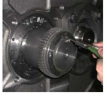
c) Fasten the M10 hexagon socket set screw [159] to retain the shaft key [157]. This set screw is self-locking and knurled type screw.
d) Set the drive sleeve on the low-stage drive hub.
e) Screw in two stud bolts into two of the upper bolt holes in the low-stage suction cover flange.
f) After applying sufficient amount of oil, or like. on both sides of the bearing cover gasket (2) [17-2], hang the gasket from the upper stud bolts and correctly attach the gasket onto the flange surface.

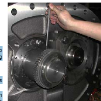
g) After slightly lifting up the high-stage block from the work bench using a lifting device, slowly move the block to approach the low-stage side. At this time, the gear coupling can be engaged smoothly if the low-stage M rotor shaft is rotated clockwise and counterclockwise alternately for a small amount.
h) Once the gear coupling has been successfully engaged, push the high-stage block onto the low-stage block along the rotor shaft axis. Then, insert 4 to 6 hexagon socket head cap screws [18-2] into the bolt holes, while avoiding the bolt holes that are adjacent to the left and right alignment pins, and temporarily fasten them evenly to eliminate the clearance between the low-stage and high-stage flanges.
i) After the flange surfaces have contacted, slightly loosen the bolts that have been temporarily fastened. Then, drive in the left and right alignment pins [19-2].
j) Rotate the low-stage M rotor using a special tool or something to check that no abnormality is found.
k) Tighten the hexagon socket head cap screws (22 in total) to the specified torque. The lower four screws [18-3] are 20 mm longer than the [18-2] screws. Care must be taken not to confuse them. These four longer screws [18-3] for fastening the lowest flange part, unlike [18-2] screws, must be tightened at the flange part from the low-stage suction cover side. When tightening the lower flange part, it is necessary to place the compressor on a special stand as well as in the case of disassembly.
5.5.15 Unloader Indicator
The unloader indicator is implemented with two micro-switches, a micro-switch cam, and a potentiometer. These parts are used to detect the change in the rotation angle of the indicator cam
shaft, which converts the axial position change of the unloader slide valve into rotational position change, convert the change into an electric signal, and send the signal to the package unit and/or the controller of the refrigeration system. To check the unloader indicator after inspection, adjustment, or parts replacement, coordination with the controller side will be required. Even in a case where the compressor is carried out of the installation site for overhaul, the indicator assembly is often removed from the compressor (to be kept at the site) and the inspection/adjustment and parts replacement are performed at the site. Thus, this section provides a detailed procedure, which may be helpful after the reassembly work.
When removing the indicator block or performing inspection/adjustment or parts replacement, be sure to shut down the control power and use lock-out and tag-out procedures. If the power is not shut down, there is a risk of electric shock.
The high-stage of 4032**C is implemented with an indicator assembly that is identical to the one used in a standard single stage compressor (except that the dial and micro-switch cam which are exclusively designed for 4032**C high-stage, for the range of 30 to 100 %). On the low-stage of 4032**C, a standard indicator assembly is mounted on the special fixture for 4032**C low-stage that converts the axial direction of the indicator assembly to the lateral direction.
5.5.15.1 Potentiometer
The potentiometer [129] of the standard type indicator is a rotary instrument for measurement over a full turn. It senses the continuously variable position (indicated load of 0% to 100%) of the unloader slide valve, and feeds the sensed position as electric signals to the control side of the package unit or refrigerating system. While the expected service life of the potentiometer will significantly vary depending on the installation environment of the compressor (e.g. corrosive gas atmosphere, moisture, etc.) and operational conditions (e.g. frequent partial load operations, frequent start/stop operation, vibration, etc.), the potentiometer is a consumable part that requires regular replacement according to the situation.
■ Disassembly
Refer to Section 5.4.1 in this manual for the low-stage/high-stage disassembly procedure.
■ Inspection
a) Check at the terminal block that the lead wires of the potentiometer are not loosened.
b) Check for any crack or other defects in the soldering of the lead wires of the potentiometer.
c) Manually rotate the shaft of the potentiometer and measure the resistance value using a circuit tester to check that the resistance value changes smoothly.
5.5.15.2 Micro-switches and Micro-switch Cam
The unloader indicator uses two micro-switches [125] and one micro-switch cam [127] to detect the commanded 0% (30% for the high-stage) and 100% capacity control positions of the unloader slide valve. If the micro-switch fails or any of these connections becomes loose for some reason, correct position detection cannot be made, and it causes a problem in the operation control of the compressor.
■ D isassembly
Refer to Section 5.4.1 in this manual for the low-stage/high-stage disassembly procedure.
■ Inspection
a) In the normal condition where the hydraulic line for the capacity control of the compressor is not opened, set the unloader piston to the no load and full load positions from the manual capacity control circuit and check the operation of the control circuit to see if the micro-switch can detect the 0% (30%) and 100% positions of the micro-switch cam (i.e., by checking the operation of the relevant relays and contacts). If the hydraulic line for the capacity control of the compressor is opened for overhaul or other work, use nitrogen gas or compressed air to set the unloader piston to the no-load and full load positions and check if the micro-switch can detect the 0% (30%) and 100% positions of the micro-switch cam.
b) After shutting down the control power and carrying out the lock-out and tag-out procedures, remove the indicator glass and check that the micro-switch screws [126] are not loosened.
c) Check that the hexagon socket head set screw [128] securing the micro-switch cam [127] are not loosened.
d) After checking that the wiring for the micro-switch has been removed, turn on and off the switch to check the normal switching operation of the micro-switch using a circuit tester.
e) Carry out other visual inspection including any indication of water intrusion in the indicator, any rust on switch terminals, any wear of the switch roller or micro-switch cam, and so on.
5.5.15.3 Reassembly
To carry out the reassembly, follow the disassembly procedure in reverse. Lastly, correctly set the i ndicator needle (pointer) [138] position according to the following procedure:
a) If the hydraulic line for the capacity control of the compressor is opened for the purpose of overhaul or other work, use nitrogen gas or compressed air to set the unloader piston to the no-load position. Then, set and fix the indicator needle to the starting point of an illustration (on the indicator dial) which indicates rotation. Next, set the piston to the full load position. Make sure the indicator needle points to the end point of the range drawn on the dial.
b) In the normal condition where the hydraulic line for the capacity control is not opened, use the manual capacity control circuit to move the piston. While the control power is turned on, the indicator cover [146] must be mounted to prevent possible electric shock. Then, after the piston position is fixed, control power is turned off, and the lock-out and tag-out procedures are completed, remove the indicator cover and secure the indicator needle in position.
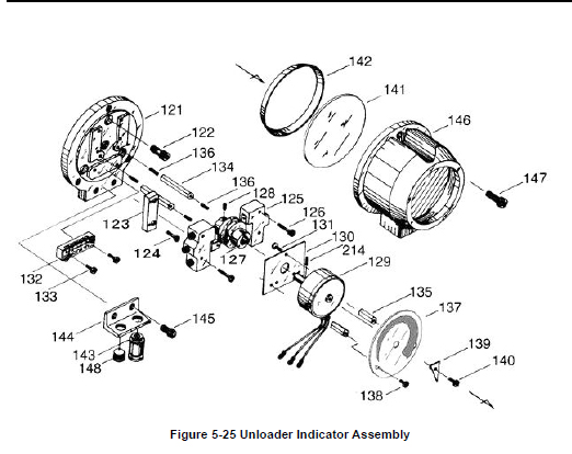
Table 5-12 Component Parts of the Unloader Indicator Assembly
P/N Part Name Q'ty P/N Part Name Q'ty
121 Micro-switch base plate 1 136 Hexagon socket set screw, M3 × 14 3
122 Hexagon socket head cap screw, M6 × 20 3 137 Dial, 30 to 100 % 1
123 Micro-switch base plate 1 137 Dial, 0 to 100% 1
124 Phillips Screw, M3 × 10 2 138 Phillips Screw, M3 × 5 2
125 Micro-switch 2 139 Indicator needle 1
126 Phillips Screw, M3 × 25 4 140 Phillips Screw, M3 × 10 1
127 Micro-switch cam, 30 to 100 % 1 141 Indicator glass 1
127 Micro-switch cam, 0 to 100 % 1 142 Indicator glass spacer 1
128 Hexagon socket set screw, M4 × 8 1 143 Electric cable gland 1
129 Potentiometer 1 144 Bracket, 125L 1
130 Potentiometer mounting plate 1 145 Hexagon socket head cap screw, M6 × 15 2
131 Phillips Screw, M3 × 5 3 146 Unloader indicator cover (2) 1
132 Terminal block 1 147 Hexagon socket head cap screw, M6 × 15 3
133 Phillips Screw, M3 × 20 2 148 Plug 1
134 Dial plate support [2] 2 214 Spring pin 2 dia. × 8 1
135 Dial plate support [1] 2 265-2 Spring washer, M3 7
Note: For the items 127 and 137, the range of 30 to 100% is specified for the high-stage and the
range of 0 to 100% is specified for the low-stage.
Chapter 6 Troubleshooting
Table 6-1 describes typical trouble symptoms of compressors, their causes and actions to be taken. The explanations of this Chapter are assumed that the compressor is used in the general refrigeration cycle.
Table 6-1 Troubleshooting
01: Compressor does not start up
Direct cause Root cause Action
Power source is off. Mostly caused by forgetting to turn on after inspection. Use a check sheet for post-inspection actions and implement finger pointing and call check to prevent forgetting.
Main motor failure Mostly caused by activation of overload protection circuit. Refer to the operation manual of the motor for details including other causes and actions.
"Micro-switch and micro-switch cam" of the indicator do not sense capacity control of 0 %. Micro-switch failure Replace. Loosening of micro-switch or micro-switch cam set screw due to vibration. Adjust the position of the cam and switch, and tighten them. Use thread locking agent if necessary. When compressor's vibration is unusually high, see Item No. 12 "Compressor generates abnormal vibration and/or sound".
Too slowly to sense capacity control of 0 % due to defective capacity control oil supply line Improper adjustment of oil flow control valve (throttled excessively). Readjust. Leak/clogging in piping or solenoid valve Remove cause, and check oil for contamination/replace oil.
Oil pressure not detected Failure of oil pressure protection device, pressure sensor, relay, etc. Identify defective devices, investigate causes of failure and take necessary actions. Then, replace failed device(s). Pressure pipe is clogged. Remove clogging, and check oil for contamination/replace oil.
Cooling water circulation is not confirmed. Failure of devices such as cooling water pump and related circuits Identify defective devices, investigate causes of failure and take necessary
actions. Then, replace failed device(s).
Circulation route is clogged. Remove the clogging. Failure of magnet, relay, etc. in compressor startup circuit Aging degradation Replace with new one. Poor installation environment Replace ventilation fans, etc. if defective. Improve temperature, humidity and ventilation at the installation site.
02: Compressor stops immediately after startup
Low pressure protection circuit activates. Insufficient refrigerant flow Insufficient refrigerant To correct insufficient refrigerant, check leak, stop leak and then add refrigerant. * Also pay attention to moisture entering into the system.
Low pressure protection circuit activates. Insufficient refrigerant flow Insufficient liquid supply To correct insufficient liquid supply, inspect expansion valve and liquid supply strainer. Take necessary actions. In addition, inspect devices and parameters (set values) of the expansion valve aperture adjusting mechanism, and take necessary actions. Heat exchange failure in heat
exchanger If there are any problem (insufficiency) in heat exchange, such as malfunction of defrosting, investigate the cause and take necessary actions. In case of malfunction of pressure
control valve, replace the valve or remove the cause. Failure of low pressure protection device, pressure sensor, relay, etc. Identify defective devices, investigate causes of failure and take necessary actions. Then, replace failed device(s).
Motor overload Motor overload that occurs just after startup is mostly caused not by the refrigeration cycle but by the motor. Refer to the instruction manual of the motor.
03: Unusually low pressure (decrease of suction pressure)
Refer to direct cause, "Low pressure protection circuit activates", in Item 02 above.
04: Low oil pressure (low lubricating oil supply pressure)
Oil filter element is clogged. * Pressure difference between the outlet port and inlet port is large. Contamination of lubricating oil Remove clogging, and check oil for contamination/replace oil.
Internal defects of compressor Check for oil contamination and conduct vibration/noise diagnosis. Overhaul compressor if necessary.
Insufficient oil in oil separator. Oil heater is not functioning, refrigerant dissolves excessively when the machine is stopped, and oil loss occurs at startup. Inspect oil heater alone, inspect relays, etc. on related circuits, and replace parts as necessary. Insufficient oil return due to insufficient refrigerant circulation Correct insufficient refrigerant circulation, and return oil from load-side heat exchanger. * Supply lubricating oil temporarily. Troubles such as clogging in oil return passage Remove causes of the trouble, and restore the system.
Chapter 7 Related Documents
7.1 Development Views, Assembly Sectional Views
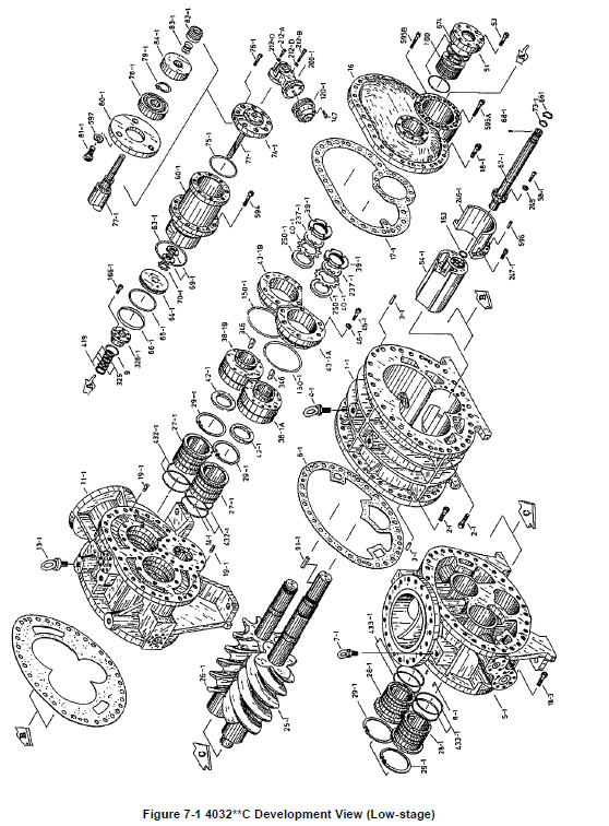
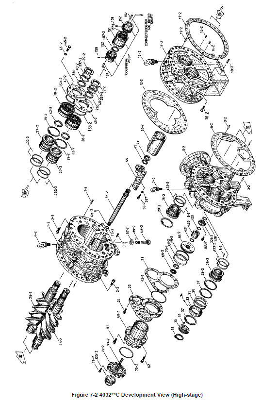
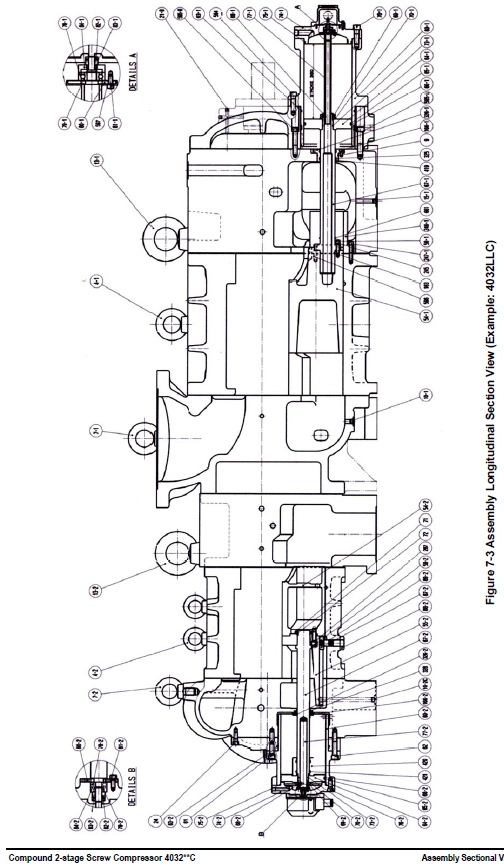
7.2 Parts Configuration Table
No. Part Name Code No. Remarks Q’ty.
1-1 Main Rotor Casing (1) CS00100-400S 400S** 1(S*C)
1-1 Main Rotor Casing (1) - 400M** 1(M*C)
1-1 Main Rotor Casing (1) - 400L** 1(L*C)
1-1 Main Rotor Casing (1) - 400LL* 1 (LL*C)
1-1 Main Rotor Casing (1) - 400XL* 1(XL*C)
1-2 Main Rotor Casing (2) CS00100-320S 4032*SC 1(*SC)
1-2 Main Rotor Casing (2) CS00100-320M 4032*MC 1(*MC)
1-2 Main Rotor Casing (2) CS00100-320L 4032*LC 1(*LC)
1-2 Main Rotor Casing (2) CS00100-320LL 4032*LLC 1(*LLC)
2-1 Hexagon Socket Head Cap Screw NB35930-110
M30×110
with captive washer 60
2-2 Hexagon Socket Head Cap Screw NB35424-08D M24×80 52
3-1 Alignment Pin NE2330-100A Φ30×100 4
3-2 Alignment Pin NE2325-080A Φ25×80 4
4-1 Eye Bolt NB600-42 M42 2
4-2 Eye Bolt NB600-30 M30 2
5-1 Suction Cover (1) CS00501-4032C1 4032**C 1
5-2 Suction Cover (2) CS00501-4032C2 4032**C 1
6-1 Gasket, Suction Cover (1) CS00600-4032CN 4032**C 1
6-2 Gasket, Suction Cover (2) CS00600-320N 320*** 1
7-1 Eye Bolt NB600-42 M42 2
7-2 Eye Bolt NB600-36 M36 1
8-1 Spring Pin (1) NE3208-025 Φ8×25 2
8-2 Spring Pin (2) NE3206-018 Φ6×18 2
9 O-ring PA12-095 JIS B 2401 G95 1
10-1 Plug NF021-NPT04 NPT1/2 1
10-2A Plug NF02 ーNPT06 NPT3/4 1
10-2B Plug NF02 ーNPT06 NPT3/4 1
10-2C Plug NF021NPT04 NPT1/2 1
11-1 Bearing Head (1) CS01100-4032C1 4032**C 1
11-2 Bearing Head (2) CS01100-4032C2 4032**C 1
12-1 Gasket, Bearing Head (1) CS01200-400 400V** 1
12-2 Gasket, Bearing Head (2) CS01200-320N 320*** 1
13-1 Eye Bolt NB600-64 M64 2
13-2 Eye Bolt NB600-64 M64 2
14-1 Spring Pin (1) NE3208-025 Φ8×25 2
14-2 Spring Pin (2) NE3206-018 Φ6×18 2
15-1A Plug NF021-NPT06 NPT3/4 1
15-1B Plug NF021-NPT10 NPT1 1/4 1
15-2A Plug NF06-020 R3/4 1
15-2B NF021-NPT06 NPT3/4 2
16 Bearing Cover CS01600-4032C 4032**C 1
17-1 Gasket, Bearing Cover (1) CS01700-400 400V** 1
17-2 Gasket, Bearing Cover (2) CS01700-4032CN 4032**C 1
No. Part Name Code No. Remarks Q’ty.
18-1 Hexagon Socket Head Cap Screw NB35930-100
M30×100
with captive washer 22
18-2 Hexagon Socket Head Cap Screw NB35424-075 M24×75 22
18-3 Hexagon Socket Head Cap Screw NB35424-095 M24×95 4
19-1 Alignment Pin with Groove and Hole NE2320-100A Φ20×100 2
19-2 Alignment Pin with Female Tread NE2325-070A Φ25×70 2
21-A Plug NF021-NPT02 NPT1/4 4
21-B Plug NF021-NPT03 NPT3/8 1
21-C Plug NF021-NPT04 NPT1/2 1
22 Balance Piston Cover CS02200-320 320*** 1
23 Gasket, Balance Piston Cover CS02300-320N 320*** 1
24 Hexagon Socket Head Cap Screw NB35416-045 M16×45 11
25-1 Male Rotor (1)
- 4032S*C 1(S*C)
26-1 Female Rotor (1)
25-1 Male Rotor (1)
- 4032M*C 1(M*C)
26-1 Female Rotor (1)
25-1 Male Rotor (1)
- 4032L*C 1(L*C)
26-1 Female Rotor (1)
25-1 Male Rotor (1)
- 4032LL*C 1 (LL*C)
26-1 Female Rotor (1)
25-1 Male Rotor (1)
- 4032XL*C 1(XL*C)
26-1 Female Rotor (1)
25-2 Male Rotor (2)
- 4032*SC 1(*SC)
26-2 Female Rotor (2)
25-2 Male Rotor (2)
- 4032*MC 1(*MC)
26-2 Female Rotor (2)
25-2 Male Rotor (2)
- 4032*LC 1(*LC)
26-2 Female Rotor (2)
25-2 Male Rotor (2)
- 4032*LLC 1(*LLC)
26-2 Female Rotor (2)
27-1 Main Bearing (1) O-ring type CS0270-4032N No.27-1 + No.432-1 2
27-2 Main Bearing (2) O-ring type CS0270-GRT No.27-2 + No.432-2 2
28-1 Side Bearing (1) O-ring type CS02800-4032N No.28-1 + No.438-1 2
28-2 Side Bearing (2) O-ring type CS0280-GRT No.28-2 + No.438-2 2
29-1 Snap Ring (1) C type Internal NG11-250 JIS B 2804 H250 4
29-2 Snap Ring (2) C type Internal NG11-200 JIS B 2804 H200 4
30 Balance Piston CS03000-320 320*** 1
31 Key, Balance Piston CS03100-320 320*** 1
32 Snap Ring C type External NG12-100 JIS B 2804 S100 1
33 Sleeve, Balance Piston CS03300-320 320*** 1
34 Set Screw NE3206-014 Φ6×14 1
35 O-ring PA12-190 JIS B 2401 G190 1
36 Spacer CS03600-320 320*** 1
37 Snap Ring C type Internal NG11-200 JIS B 2804 H200 2
38-1A Thrust Bearing (1) TPTB CS03800-T400M
400*** for M rotor
Daido
1
38-1B Thrust Bearing (1) TPTB CS03800-T400F
400*** for F rotor
Daido
1
38-2 Thrust Bearing (2) Ball type CS03800-320 320** Cast Retainer 2
No. Part Name Code No. Remarks Q’ty.
38-2 Thrust Bearing (2) TPTB CS03800-T00320 320*** 2
39-1 Lock Nut (1) NG311-028 AN28 2
39-2 Lock Nut (2) NG311-021 AN21 2
40-1 Lock Washer (1) NG32-028X AW28X 2
40-2 Lock Washer (2) NG32-021 AW21 2
42-1 Spacer, Thrust Bearing Alignment (1) CS04200-B400 400*** Booster 2
42-2 Spacer, Thrust Bearing Alignment (2) CS04200-320 320*** 2
42-2 Spacer, Thrust Bearing Alignment (2) CS04200-320TP 320*** for TPTB 2
43-1A Thrust Bearing Gland (1A) CS04300-400M 400*** for M Rotor 1
43-1B Thrust Bearing Gland (1B) CS04300-400F 400*** for F Rotor 1
43-2 Thrust Bearing Gland (2) CS04300-320 320*** 2
43-2 Thrust Bearing Gland (2) CS04300-320TP 320*** for TPTB 2
45-1 Hexagon Socket Head Cap Screw NB35420-075 M20×75 12
45-2 Hexagon Head Bolt NB111020-055 M20×55 8
46-1
Spring Washer
for Hex Socket Head Cap Screw ND330-20 400*** M20 12
46-2 Conical Spring Washer ND150-020 320*** M20 8
51 Seal Cover CS05100-400 400*** 1
53 Hexagon Socket Head Cap Screw NB35416-040 M16×40 8
54-1 Unloader Slide Valve (1-1) (L Port) CS05400-4032S1L 4032S*C 1(S*C)
54-1 Unloader Slide Valve (1-1) (M Port) CS05400-4032S1M 4032S*C 1(S*C)
54-1 Unloader Slide Valve (1-1) (L Port) CS05400-4032M1L 4032M*C 1(M*C)
54-1 Unloader Slide Valve (1-1) (M Port) CS05400-4032M1M 4032M*C 1(M*C)
54-1 Unloader Slide Valve (1-1) (L Port) CS05400-4032L1L 4032L*C 1(L*C)
54-1 Unloader Slide Valve (1-1) (M Port) CS05400-4032L1M 4032L*C 1(L*C)
54-1 Unloader Slide Valve (1-1) (L Port) CS05400-4032LL1L 4032LL*C 1 (LL*C)
54-1 Unloader Slide Valve (1-1) (M Port) CS05400-4032LL1M 4032LL*C 1 (LL*C)
54-1 Unloader Slide Valve (1-1) (L Port) CS05400-4032XL1L 4032XL*C 1(XLLLC)
54-1 Unloader Slide Valve (1-1) (M Port) CS05400-403X2L1M 4032XL*C 1(XLLLC)
54-2 Unloader Slide Valve (1-2) (L Port) - 4032*SC 1(*SC)
54-2 Unloader Slide Valve (1-2) (M Port) - 4032*SC 1(*SC)
54-2 Unloader Slide Valve (1-2) (L Port) - 4032*MC 1(*MC)
54-2 Unloader Slide Valve (1-2) (M Port) - 4032*MC 1(*MC)
54-2 Unloader Slide Valve (1-2) (L Port) - 4032*LC 1(*LC)
54-2 Unloader Slide Valve (1-2) (M Port) - 4032*LC 1(*LC)
54-2 Unloader Slide Valve (1-2) (L Port) - 4032*LLC 1(*LLC)
54-2 Unloader Slide Valve (1-2) (M Port) - 4032*LLC 1(*LLC)
55 Unloader Slide Valve (2-2) - 320S** 1(S*C)
55 Unloader Slide Valve (2-2) - 320M** 1(M*C)
55 Unloader Slide Valve (2-2) - 320L** 1(L*C)
55 Unloader Slide Valve (2-2) - 320LL* 1 (LL*C)
58-1 Hexagon Socket Head Cap Screw NB35414-055 M14×55 8
58-2 Hexagon Socket Head Cap Screw NB35416-050 M16×50 4
60-1 Unloader Cylinder (1) CS06000-400S 4032S*C 1(S*C)
60-1 Unloader Cylinder (1) CS06000-400M 4032M*C 1(M/L/LL)
(XL*C)
60-2 Unloader Cylinder (2) CS06000-320S 320S** 1(*SC)
60-2 Unloader Cylinder (2) CS06000-320M 320M** 1(*MC)
No. Part Name Code No. Remarks Q’ty.
60-2 Unloader Cylinder (2) CS06000-320L 320L** 1(*LC)
60-2 Unloader Cylinder (2) CS06000-320LL 320LL* 1(*LLC)
61 Hexagon Socket Head Cap Screw NB35420-050 M20×50 2
62 Hexagon Socket Head Cap Screw NB35420-110 M20×110 6
63-1 O-ring PA12-250 JIS B 2401 G250 1
63-2 O-ring PA12-240 JIS B 2401 G240 1
64-1 Unloader Piston (1) CS06400-400 400V** 1
64-2 Unloader Piston (2) CS06400-320S 320*** 1
65-1 O-ring PA11-215 JIS B 2401 P215 1
65-2 O-ring PA11-200 JIS B 2401 P200 1
66-1 Teflon Cap Seal CS06600-400 CAP-3BE-215 1
66-2 Teflon Cap Seal CS06600-320 CAP-3BE-200 1
67-1 Unloader Push Rod (1) CS06700-4032S 4032S*C 1(*SC)
67-1 Unloader Push Rod (1) CS06700-4032M 4032M*C 1(*MC)
67-1 Unloader Push Rod (1) CS06700-4032L 4032L*C 1(*L/*LLC)
67-2 Unloader Push Rod (2) CS06700-320SU 320S** 1(*SC)
67-2 Unloader Push Rod (2) CS06700-320MU 320M** 1(*MC)
67-2 Unloader Push Rod (2) CS06700-320LU 320L** 1(*LC)
68-1 Guide Pin (1) NE2506-016 Φ6×16 1
68-2 Guide Pin (2) NE2506-016 Φ6×16 1
69-1 Lock Nut (1) NG31-010 AN10 2
69-2 Lock Nut (2) NG31-010 AN10 1
70-1 Lock Washer (1) NG32-010 AW10 1
70-2 Lock Washer (2) NG32-010 AW10 1
71 Lock Nut NG31-012 AN12 1
72 Lock Washer NG32-012 AW12 1
73-1 O-ring PA12-045 JIS B 2401 G45 1
73-2 O-ring PA11-044 JIS B 2401 P44 1
74-1 Unloader Cover (1) CS07400-400 4032**C 1
74-2 Unloader Cover (2) CS07400-320 320*** 1
75-1 O-ring PA12-220 JIS B 2401 G220 1
75-2 O-ring PA12-210 JIS B 2401 G210 1
76-1 Hexagon Socket Head Cap Screw NB35422-070 M22×70 8
76-2 Hexagon Socket Head Cap Screw NB35416-040 M16×40 8
77-1 Indicator Cam (1) CS07700-400S 400VS* 1(S*C)
77-1 Indicator Cam (1) CS07700-400M 400VM* 1(M*C)
77-1 Indicator Cam (1) CS07700-400VL 400VL* 1(L*/LL*C)
77-2 Indicator Cam (2) CS07700-320S 320S** 1(*SC)
77-2 Indicator Cam (2) CS07700-320M 320M** 1(*MC)
77-2 Indicator Cam (2) CS07700-320L 320L** 1(*LC)
77-2 Indicator Cam (2) CS07700-320LL 320LL** 1(*LLC)
78-1 Ball Bearing CS07800-400 #6302 1
78-2 Ball Bearing CS07800-200 #6000 1
79-1 Snap Ring C type External NG12-015 JIS B 2804 S15 1
79-1 Snap Ring C type External NG12-010 JIS B 2804 S10 1
80-1 Bearing Gland (1) CS08000-400 400*** 1
80-2 Bearing Gland (2) CS08000-200 200*** 1
No. Part Name Code No. Remarks Q’ty.
81-1 Hexagon Socket Head Cap Screw NB35406-015 M6×15 3
81-2 Hexagon Socket Head Cap Screw NB35406-015 M6×15 3
82-1 V-ring CS08200-200B VH10 NBR 1
82-2 V-ring CS08200-200B VH10 NBR 1
83-1 Spring CS08300-200 200*** 1
83-2 Spring CS08300-200 200*** 1
84-1 Retainer, Indicator Cam Spring CS08400-400 400*** 1
84-2 Retainer, Indicator Cam Spring CS08400-200 200*** 1
87-2 Guide Block (2)
CS08700-320 320*** 1
88-2 Stem, Guide Block (2)
89-2 O-ring PA11-024 JIS B 2401 P24 2
91 Shaft Key CS09100-400 400*** 1
92-1 Suction Flange (1) with hole CZA01-300C16B ANSI #300 16" 1
92-2 Suction Flange (2) with hole CZA01-300C12B ANSI #300 12" 1
93-1 Gasket, Suction Flange (1) PL300-400 ANSI #300 16" 1
93-2 Gasket, Suction Flange (2) PL300-300 ANSI #300 12" 1
94-1 Stud Bolt NBU611/4-7UNC
1-1/4"
-7UNC×165mm
20
- Hexagonal Nut, Stud Bolt NCU1511/4-7UNC 1-1/4" -7UC 20
94-2 Stud Bolt NBU611/8-7UNC
1-1/8"
-7UNC×150mm
16
- Hexagonal Nut, Stud Bolt NCU1511/8-7UNC 1 1/8" -7UC 16
95-1 Discharge Flange (1) with hole CZA01-300C12B ANSI #300 12" 1
95-2 Discharge Flange (2) with hole CZA01-300C08B ANSI #300 8" 1
96-1 Gasket, Discharge Flange (1) PL300-300 ANSI #300 12" 1
96-2 Gasket, Discharge Flange (2) PL300-200 ANSI #300 8" 1
97-1 Stud Bolt NBU611/8-7UNC
1-1/8"
-7UNC×150mm
16
97-2 Stud Bolt NBU607/8-9UNC 7/8" -9UNC×120mm 12
100 Mechanical Seal Assembly CS10000-400 400*** BOD 1
100 Mechanical Seal Assembly CS10001-400BBDR 400*** BBDⅡ FKM 1
100 Mechanical Seal Assembly CS1002-400EBD 400*** BBD-E 1
120-1 Unloader Indicator Assembly (1) CS12000-200F 200** 0-100% 1
120-2 Unloader Indicator Assembly (2) CS12000-3225 3225C (2) 30-100% 1
125 Micro-Switch CS12500-200 200*** Z15GW 4
127-1 Micro-Switch Cam (1) CS12700-200F 200*** 0-100% 1
127-2 Micro-Switch Cam (2) CS12700-322530 3225C (2) 30-100% 1
128 Hexagon Socket Head Set Screw NA83604-005 M4×5 2
129 Potentiometer 200-1 k CS1299-E10 with lead wire 2
137-1 Indicator Dial (1) CS13700-200 200*** 1
137-2 Indicator Dial (2) CS13700-3225C 3225C (2) 30-100% 1
150-1 O-ring PA12-290 JIS B 2401 G290 2
150-2 O-ring PA12-220 JIS B 2401 G220 2
151 Drive Sleeve
CS15100-4032CN
4032**C 1
152 Drive Hub 4032**C 2
157 Key, Driven Hub & Drive Hub CS15700-4032CH
24×16×111
single round 2
159 Set Screw NA83610-016 M10×16 2
163 O-ring PA12-065 JIS B 2401 G65 1
No. Part Name Code No. Remarks Q’ty.
166-1 Hexagon Socket Head Cap Screw NB35412-025 M12×25 4
166-2 Hexagon Socket Head Cap Screw NB35405-010 M5×12 4
187-1 Snap Ring C type External NG12-095 JIS B 2804 S95 1
187-2 Snap Ring C type External NG12-095 JIS B 2804 S95 1
200-1 Unloader Indicator Fixture Assembly CS20000-400 400V** 1
201 Bevel Gear (1) CS20100-1612C9 1612LSC(Φ9) 1
202 Bevel Gear (2) CS20100-1612C6 1612LSC(Φ6) 1
206 Glass Gland, Unloader Indicator CS20600-1612 1612LSC 1
208 Shaft, Unloader Indicator CS12200-400 400V** 1
208-A Snap Ring C type External NG12-010 S10 2
208-B Bearing CS16460-200 #6000LL 2
210 Cross-recessed and Pan Head Screw NB35405-015 M5×15 4
212-A Hexagon Socket Head Cap Screw NB35405-030 M8×30 2
212-B Hexagon Socket Head Cap Screw NB35408-095 M8×95 2
212-C Hexagon Socket Head Cap Screw NB35408-020 M8×20 4
212-D Spring Washer ND320-008 M8 8
215-1a Flange, Lubricating Oil Supply (1) to
Main Journal CZA01-300C02B ANSI #300 2" 1
215-1b Flange, Lubricating Oil Supply (1) to
Side Journal CZA01-300C01B ANSI #300 1" 1
215-1c Flange, Lubricating Oil Supply to TPTB CZA01-300C02B ANSI #300 2" 1
215-2 Flange, Lubrication Oil Supply (2) to
Journal CZA01-300C02B ANSI #300 2" 1
215-2 Flange, Lubricating Oil Supply (2) to
TPTB CZA01-300C01B ANSI #300 1" 1
216-1a Flange Gasket, Lubricating Oil Supply
(1) to Main Journal PL300-050 ANSI #300 2" 1
216-1b Flange Gasket, Lubricating Oil Supply
(1) to Side Journal PL300-025 ANSI #300 1" 1
216-1c Flange Gasket, Lubricating Oil Supply to
TPTB PL300-050 ANSI #300 2" 1
216-2 Flange Gasket, Lubrication Oil Supply
(2) to Journal PL300-050 ANSI #300 2" 1
216-2 Flange Gasket, Lubricating Oil Supply
(2) to TPTB PL300-025 ANSI #300 1" 1
217-1a Stud Bolt NBU605/8-11UNC 5/8 " -11UNC×75mm 8
217-1b Stud Bolt NBU605/8-11UNC 5/8 " -11UNC×75mm 4
217-1c Stud Bolt NBU605/8-11UNC 5/8 " -11UNC×75mm 8
217-2 Stud Bolt NBU605/8-11UNC 5/8 " -11UNC×75mm 8
217-2 Stud Bolt NBU605/8-11UNC 5/8 " -11UNC×75mm 4
- Hexagonal Nut NCU1505/8-11UNC 5/8 " -11UNC 32
218 Flange, Injection Oil Supply CZA01-300C0204B ANSI #300 2-1/2" 1
219 Flange Gasket, Injection Oil Supply PL300-065 ANSI #300 2-1/2" 1
220 Stud Bolt NBU603/4-10UNC 3/4" -10UNC×90mm 8
237-1 Torsional Slip Washer (1) CS23700-400 400*** 2
237-2 Torsional Slip Washer (2) CS23700-320 320*** 2
245
Special Spring Washer for Hexagon
Socket Head Cap Screw ND330-14 No.3 14、400V** 8
246-1 Guide, Unloader Slide Valve CS24600-400 400*** 1
247-1 Hexagon Socket Head Cap Screw NB35416-075 M16×75 8
250-1 Thrust Washer (1) CS25000-400 400*** 2
250-2 Thrust Washer (2) CS25000-320 320*** 2
267 Special Spring Washer for Hexagon
Socket Head Cap Screw ND320-016 M16 4
No. Part Name Code No. Remarks Q’ty.
325 O-ring PA11-070 JIS B 2401 P70 2
326-1 Gland, O-ring (1) CS32600-400 400V** 1
326-2 Gland, O-ring (2) CS32600-320 320*** 1
328 O-ring PA11-058 JIS B 2401 P58 1
346 Shaft Key for TPTB CS34600-400 400*** 2
419 Backup Ring PBP21-070 SUN-2BP-70-T2 4
420 Spacer, Unload Position (30 % load) CS42000-320S30 320S** 1(*SC)
420 Spacer, Unload Position (30 % load) CS42000-320M30 320M** 1(*MC)
420 Spacer, Unload Position (30 % load) CS42000-320L30 320L** 1(*LC)
420 Spacer, Unload Position (30 % load) CS42000-320LL30 320LL* 1(*LLC)
421 O-ring PA11-058 JIS B 2401 P58 2
432-1 O-ring PA12-200 JIS B 2401 G200 4
432-2 O-ring PA12-165 JIS B 2401 G165 4
433-1 O-ring PA12-200 JIS B 2401 G200 4
433-2 O-ring PA12-165 JIS B 2401 G165 4
594 Hexagon Socket Head Cap Screw NB35420-075 M20×75 12
595-A Hexagon Socket Head Cap Screw NB35424-110 M24×110 10
595-B Hexagon Socket Head Cap Screw NB35420-110 M20×110 2
596 Alignment Pin NE2316-065A Φ16×65 2
597
Special Spring Washer for Hexagon
Socket Head Cap Screw ND330-06 No.3 6 3
605-A Plug NF021-NPT03 NPT3/8 3
605-B Plug NF021-NPT010 NPT1 1/4 1
661 Snap Ring C type External NG12-070 JIS B 2804 S70 1
674 O-ring for BOD type Mechanical Seal PA62-039 AS568A 261 1
- Flange, Oil drain CZA01-300C0004B ANSI #300 1/2" 1
- Flange, Oil drain CZA01-300C0004B ANSI #300 1/2" 1
- Flange, Oil drain CZA01-300C01B ANSI #300 1" 1
Flange Gasket, Oil drain CZA01-300C0004B ANSI #300 1/2" 1
Flange Gasket, Oil drain CZA01-300C0004B ANSI #300 1/2" 1
Flange Gasket, Oil drain CZA01-300C01B ANSI #300 1" 1
Stud Bolt CZA01-300C0004B 1/2" -13UNC×60mm 4
Stud Bolt CZA01-300C0004B 1/2" -13UNC×60mm 4
Stud Bolt NBU605/8-11UNC 5/8" -11UNC×75mm 4
Hexagonal Nut NCU1501/2-13UNC 1/2" -13UNC 8
Hexagonal Nut NCU1505/8-11UNC 5/8" -11UNC 4
7.3 Tightening Torques for Bolts and Nuts
P/N What is tightened
Torque
Q’ty. Size
N·m kgf·cm
2-1 Main Rotor Casing (1) to
Suction Cover (1) and Bearing Head (1) 1600 16000 60 M30×110
2-2 Main Rotor Casing (2) to
Suction Cover (2) and Bearing Head (2) 750 7500 52 M24×80
18-1 Bearing Cover to Bearing Head (1) 1600 16000 22 M30×100
18-2 Suction Cover (1) to Bearing Head (2) 750 7500 22 M24×75
18-3 Suction Cover (1) to Bearing Head (2) 750 7500 4 M24×95
24 Balance Piston Cover to Suction Cover (2) 240 2400 11 M16×45
53 Seal Cover to Bearing Cover 240 2400 8 M16×40
58-1 Unloader Push Rod (1) to Unloader Slide Valve (1-1) 140 1400 8 M14×55
58-2 Unloader Slide Valve (2-2) to Unloader Slide Valve (1-2) 240 2400 4 M16×50
61 Unloader Cylinder (2) to Balance Piston Cover 450 4500 2 M20×50
62 Unloader Cylinder (2) to
Balance Piston Cover and Suction Cover (2) 450 4500 6 M20×110
76-1 Unloader Cover (1) to Unloader Cylinder (1) 640 6400 8 M22×70
76-2 Unloader Cover (2) to Unloader Cylinder (2) 240 2400 8 M16×40
81-1 Bearing Gland (1) to Unloader Cover (1) 10 100 3 M6×15
81-2 Bearing Gland (2) to Unloader Cover (2) 10 100 3 M6×15
159 Shaft Key for Drive Hub 50 500 2 M10×25
166-1 Oil Gland (1) to Bearing Head (1) 90 900 4 M12×25
166-2 Oil Gland (2) to Bearing Head (2) 6 60 4 M5×12
212-A Indicator Fixture (A) to Unloader Cover (1) 25 250 2 M8×30
212-B Indicator Fixture (A) to Unloader Cover (1) 25 250 2 M8×95
212-C Indicator Fixture (B) to Indicator Fixture (A) 25 250 4 M8×20
247-1 Unloader Slide Valve Guide to Main Rotor Casing(1) 240 2400 8 M16×75
594 Bearing Cover to Unloader Cylinder (1) 450 4500 12 M20×75
595-A Bearing Cover to Bearing Head (1) 750 7500 10 M24×110
595-B Bearing Cover to Bearing Head (1) 450 4500 2 M20×110
Hexagon Head Bolt
P/N What is tightened Torque Q’ty. Size
N·m kgf·cm
45-1 Thrust Bearing Gland (1) 120 1200 8 M20×55
45-2 Thrust Bearing Gland (2) 60 600 8 M16×45
Stud Bolt and Hexagonal Nut
P/N What is tightened Torque N·m kgf·cm Q’ty. Size
97-1 Low-stage Gas Outlet Flange (Intermediate Pipe) 200 2000 16 M20×75
97-4 High-stage Gas Inlet Flange (Intermediate Pipe) 200 2000 16 M20×55
Lock Nut
P/N What is tightened
Tightening torque (N·m) Q’ty. Size
Standard Maximum
39-1 Thrust Bearing (1) Note 1 5347 6683 2 AN28
39-2 Thrust Bearing (2) Note 1 2259 2824 2 AN21
69-1 Unloader Piston (1) 180 - 2 AN10
69-2 Unloader Piston (2) 180 - 1 AN10
71 Unloader Slide Valve (2) 408 510 1 AN12
Tightening Angle Range of Lock Nuts for Rotors
a) After tightening the lock nut by hand, further tighten the lock nut by using a lock nut wrench until the
rotor starts to turn. Take care not to over-tighten.
b) Put a mark on the lock nut at the right side edge of the rotor groove where the stopper tongue of the
lock washer fits in, as shown in Figure 7-9.
c) From this marking position, tighten the lock nut in such a way that rotation can be stopped within the
tightening angle range shown in Table 7-3.
When measuring the angle, use an angle gauge which is set to the diameter of rotor shaft.
7.4 About the O-rings Used
7.4.1 List of O-rings Used
O-ring
Part No.
Location JIS B 2401
attached place description in Size
functional aspect
9 O-ring Gland same as left G95
35 Balance Piston Sleeve same as left G190
63-1 Unloader Cylinder (1) same as left G250
63-2 Balance Piston Cover Unloader Cylinder (2) G240
65-1 Unloader Piston (1) same as left P215
65-2 Unloader Piston (2) same as left P200
73-1 Unloader Push Rod (1) Unloader Piston (1) G45
73-2 Unloader Push Rod (2) Unloader Piston (2) P44
75-1 Unloader Cover (1) same as left G220
75-2 Unloader Cover (2) same as left G210
89-2 Guide block Stem (2) same as left P24
150-1 Thrust Bearing Gland (1) same as left G290
150-2 Thrust Bearing Gland (2) same as left G220
163 Unloader Push Rod (1) same as left G65
325 O-ring Gland (1) same as left P70
328 O-ring Gland (2) same as left P58
421 Unload Spacer (2) same as left P58
432-1 Main Bearing (1) same as left G200
432-2 Main Bearing (2) same as left G165
433-1 Side Bearing (1) same as left G200
433-2 Side Bearing (2) same as left G165
674 Seal Cover for BOD type Mechanical Seal same as left Note2
7.4.2 O-ring Materials Used for Screw Compressor
Table 7-4 List of O-ring Materials Used for Screw Compressor
(excluding mechanical seal)
Working fluid O-ring material
Ammonia
HFC NBR
CO2 FKM
HNBR
R23
FKM
Propane
Propylene
Natural gas
City gas
Helium
SCREW COMPRESSORS SPECIALIST, LLC
6614 Topper Ridge Suite 3
San Antonio, TX 78233
Phone: 210-389-4907
Fax: 866-750-6527