SCREW COMPRESSORS SPECIALIST | Customer Satisfaction Is Our Goal | SCS is a WORLDWIDE leader of Screw Compressors
* In Shop Overhaul *Machine Shop In House *Cast Iron Housing Repair *Balancing *Industrial Hard Chrome Rotor and Seal Journal *Industrial Hard Chrome Piston Rod *Laser Alignment *Fast Turn Around Time *OEM Parts *Fast Respond *OEM Paint or Customer Specification *Emergency 24-7 Service *New Compressors *Preventive Maintenance Vibration Analysis Oil Analysis *Remanufactured Compressors *Exchange Program
MYCOM V Series Compressor Service and Overhaul
Model: V Series Compressor

About MYCOM:
Mayekawa has been deeply committed to the refrigeration industry for more than 80 years. During this time Mayekawa has developed high quality, easy to handle and cost-effective thermal technology. Mayekawa offers a comprehensive range of compressors with hundreds of models developed in response to the variety of applications required in refrigeration. New gas compressors have been developed for the specific needs of gas compression systems based on our experience in applications including helium, hydrogen, water vapor, chlorine, hydrogen chloride, and hydrogen sulfide( not including oxygen and acetylene). Mayekawa never cease building on MYCOM experience with research and development to constantly improve their compressor products.


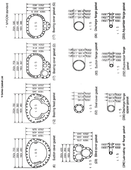
- 1. General Description of Mycom V-Series Compressor
- 1.1 Refrigerant Compression Mechanism
- 1.2 Explanation of Vi (Internal Volumetric Ration)
- 1.3 Reasons for Adjusting Vi
- 1.4 Variable Vi Mechanism
- 1.5 External Adjustment of Vi
- 1.6 Other Component Mechanisms
- 2. Exploded View of V-Series Screw Compressor
- 2.1 Parts List
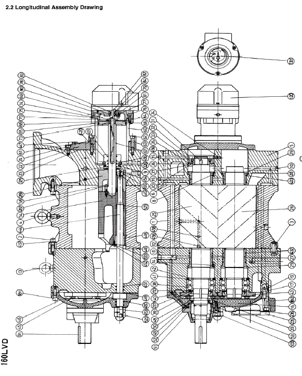
- 2.2 Longitudinal Assembly Drawing
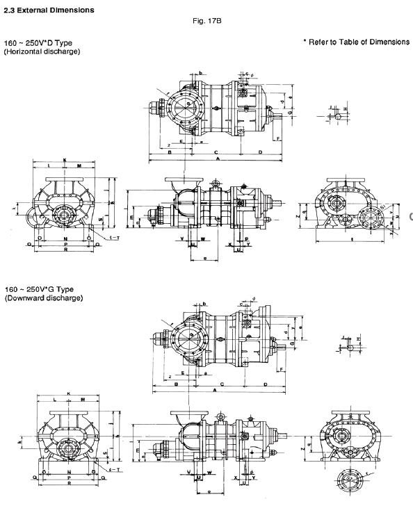
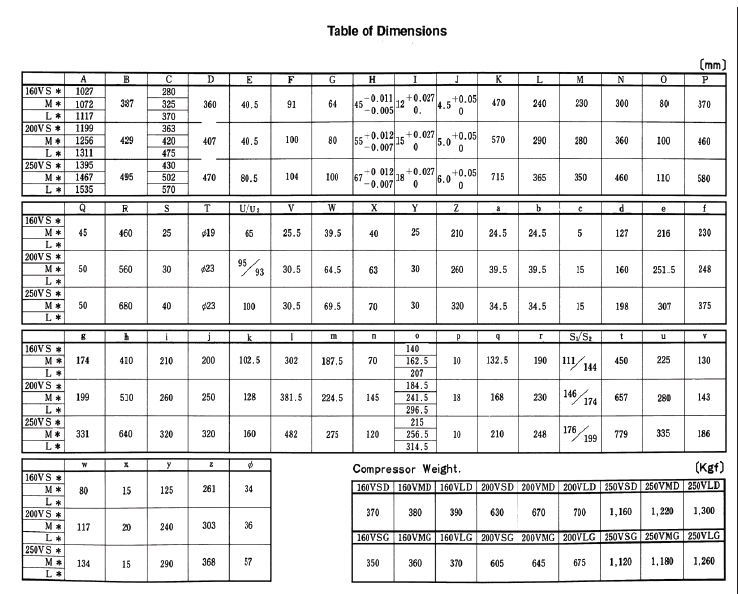
- 2.3 External Dimensions
- 3. Disassembly of V-Series
- 3.1 Preparations for Disassembly
- 3.2 Hand Tool Kit
- 3.3 Removing Compressor
- 3.4 Disassembly Sequence
- 3.4.1 Mechanical Seal
- 3.4.2 Unloader Indicator
- 3.4.3 Unloader Cover
- 3.4.4 Unloader Piston and Unloader Cylinder
- 3.4.5 Blind Cover
- 3.4.6 Balance Piston and Balance Piston Sleeve Portion
- 3.4.7 Bearing Cover
- 3.4.8 Thrust Bearing
- 3.4.9 Suction Cover and Side Bearing
- 3.4.10 Rotor, Rotor Casing and Variable Vi Slide Valve
- 3.4.11 Bearing Head and Main Bearing
- 4. Reassembly
- 4.1 Bearing Head and Main Bearing
- 4.2 Rotor Casing, Unloader Slide Bearing, Variable Vi Slide Valve and Bearing Head
- 4.3 Rotor Casing and Rotors
- 4.4 Suction Cover
- 4.5 Thrust Bearing
- 4.6 Bearing Cover
- 4.7 Blind Cover, Unloader Cylinder and Unloader Piston
- 4.8 Unloader Cover
- 4.9 Mechanical Shaft Seal
- 5. Disassembly and Adjustment of Unloader Indicator
- 5.1 Disassembly of Unloader Indicator
- 5.2 Inspection
- 5.3 Assembly and Adjustment
- 6. Standards of Components
Introduction
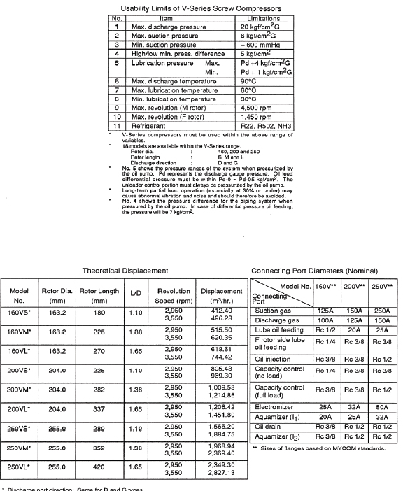
The MYCOM V-Series Screw Compressor (referred to hereafter as the “V Series”) incorporates numerous improvements. A variable Vi mechanism allows these compressors to be adjusted readily for most operating conditions and a new tooth profile (0 profile) has been introduced to further improve performance. The basic construction of the V Series is the same as standard MYCOM compressors except for the addition of the variable Vi mechanism. The operator should have a thorough knowledge of the compressor and the system it is incorporated into before attempting to disassemble the unit for inspection. Read this instruction manual carefully before undertaking any work on the system. This screw compressor is classified as a positive displacement rotary type. It compresses the refrigerant gas continuously using the volume change between two rotating screw profile rotors. Refrigerant gas is trapped in the clearance between the two mated rotors and pressure increased by decreasing the volume. The refrigerant is then discharged as a high-pressure gas.
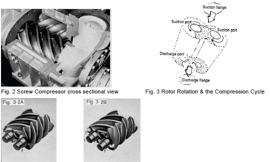
1.1 Refrigerant Compression Mechanism
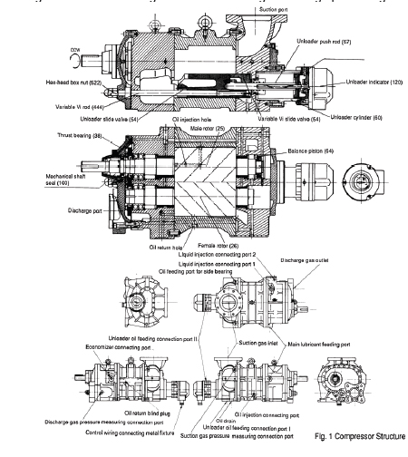
As shown in Figs. 1 and 2, a pair of mated helical gears, or rotors, are mounted in the compressor casing. The rotor having the four-lobe section is called the male (M) rotor while the one with the sixlobe section is called the female (F) rotor. A two-pole motor connected directly to the M rotor drives the compressor at speeds of 2,950 rpm or 3,550 rpm (50 Hz or 60 Hz) Compressor efficiency is directly related to the shape of the rotor lobes. In the case of the V-Series, the rotors have unsymmetrical profiles in contrast to conventional screw compressor rotor lobes. This unsymmetrical design reduces the triangular blow off hole between the casing and the rotors to 60%, minimizing leakage due to the pressure difference. Normally, an oil film seals the clearance between the leading edges of the rotor lobes and the casing. With the V-Series, however, a change has been incorporated to raise the pressure of the oil film and the clearance between the casing and the lobe leading edges is wedge shaped.
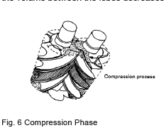
1.1.1 Suction Phase (refer to Figs. 4 and 5)
As shown in Fig. 4, the rotors of different lobe shape mate and the clearance between the M and F rotors and the casing expands gradually from the suction side as the rotors rotate. When the clearance reaches maximum as the rotors rotate further, it is sealed by the walls at both ends of the rotor and becomes independent.
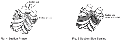
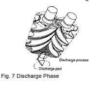
1.1.2 Compression Phase (refer to Fig. 6)
As the rotors further rotate, the suction side of the clearance is sealed by the mating of the lobes and the volume between the lobes decreases while the sealing line moves toward the discharge side.
1.1.3 Discharge Phase (refer to Fig. 7)
When the volume is decreased to the designated Vi, the clearance between the discharge port and the rotors is linked and the refrigerant is pushed to the discharge side.
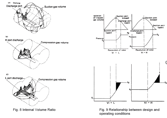
1.2 Explanation of Vi (Internal Volumetric Ratio)
In the case of a reciprocating compressor, the volume of the refrigerant sucked into the cylinder decreases and the refrigerant pressure increases as the piston ascends. When the pressure exceeds the discharge side pressure plus the force of the spring on the discharge plate valve, the refrigerant in the cylinder pushes open the valve and passes to the discharge side. In the case of the screw compressor, a volume of refrigerant is sucked into the groove between the rotors and the volume decreases while pressure increases as the rotors rotate. The process up to this point is the same as for a reciprocating compressor. When the volume is decreased to the designed Vi, the groove is linked to the discharge port and the refrigerant is pushed out. The groove is linked to the discharge port according to the volume of the groove and is not dependent on internal pressure. Vi (internal volumetric ratio) is used to represent the value of the decreased volume of suction refrigerant when the groove aligns with the discharge port (or is discharged).
This can be expressed as follows:
Vi = Volume of suction refrigerant when compression begins Volume of same quantity of refrigerant at discharge port In other words, Vi is the ratio of the groove volume after competition of suction to the volume when the discharge port opens. Conventional screw compressors have three fixed Vi values, that is 2.63, 3.65 and 5.80, termed “L port,” “M port” and “H port,” respectively.
The relationships are:
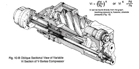
Vi = (Pd/Ps)1/k or Vik = Pd/Ps
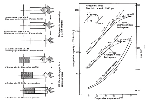
Consequently, the Vi corresponding to the compression ratio changes according to the refrigerant used. For approximate values, refer to the graph given in Fig. 12. The new V-Series, Maximizer Series Screw Compressors, are designed so that the Vi can be adjusted on site according to operating conditions.
1.3 Reasons for Adjusting Vi
Operating conditions of refrigeration systems are not always constant. As well, the same model of compressor may be operated under a variety of pressure conditions, e.g., air conditioning, cold storage and freezing applications. In the case of air conditioning and cold storage, the conditions will vary depending on the need for cooling, heating, low and high temperature. Needless to say, compressors must be operated at maximum efficiency under various conditions. The drawback of the conventional compressor is that a fixed Vi is established for the compressor during production. This Vi can later be changed by machining the compressor but is limited to change from a higher to a lower value only. Variable Vi screw compressors in the Maximizer Series were developed as an answer to this drawback. Many compressors of this type are used in special reefer carrier applications, but because of the sophisticated structure and relatively high cost, they have not been popular for general applications.
The V-Series, which incorporates a variable Vi, has consequently been developed for these general applications.
The Vi of the V-Series can be readily changed between L, M and H at the installation plant according to operating conditions.
With the fixed Vi of a conventional compressor, maximum efficiency can only be obtained when the system is operating at a pressure equivalent to the designed Vi. Unnecessary power is consumed, however, when pressure conditions diverge from the designed value. For example, if low compression ratio (high compression pressure or low discharge pressure) operation is carried out using a conventional M port compressor (designed for a medium compression ratio), compression will exceed discharge pressure and power will be wasted.
Conversely, if the same M port compressor is used under high compression conditions (high suction pressure or high discharge pressure), the discharge port opens before internal pressure has increased sufficiently, allowing refrigerant to flow back from the discharge port. Power is also wasted. Obviously, if a compressor is to be operated for an extended period under varying conditions, a variable Vi design is preferable to a fixed Vi type. For a conventional compressor with a high Vi, the discharge port can be machined to lower the Vi but a unit with a low Vi cannot be changed to a high Vi type. If a higher Vi is needed, the compressor must be replaced with a new one.
1.4 Variable Vi Mechanism
The Vi of a conventional screw compressor is determined by the combination of the axial discharge port of the rotors on the bearing head and the radial discharge port of the shaft (radial discharge port on the unloader slide valve). In the case of a conventional model, the axial and radial elements are combined to exhibit particular characteristics at partial load. In the case of V-Series compressors, the Vi can be changed by altering the size of the radial port while maintaining the axial port at Vi 5.10.
As shown in Fig. 10A, the radial port of a conventional model becomes larger as Vi becomes smaller. In the case of V-Series compressors, the stop position of the variable Vi unloader slide valve moves to the discharge side and changes Vi by reducing the size of the radial port at full load operation. As Fig. 11 shows, the refrigeration capacity changes only slightly under various Vi and other conditions. Refrigeration capacity is influenced considerably by shaft power but changes little in response to slight changes in operating conditions, as the diagram shows, consequently, once Vi is adjusted to the operating conditions, it is not necessary to alter it in response to slight changes in operating conditions.
The Vi must be adjusted only when there are major changes in operating conditions such as a change in the application of the compressor. For instance, when the operating conditions of the compressor are changed from cooling at approx. 0C evaporative temperature to refrigeration at -40 C evaporative temperatures with the compressor Vi set to the L port configuration, shaft power must be double. In such a case it is advisable to change the Vi to the H port configuration. Similarly, if the compressor is to be used for refrigeration at an evaporative temperature of 0C-30C, it is advisable to set the Vi to the M port configuration. Temperature drops and the compression ratio “Vi” increases as refrigeration progresses but Vi should not be changed according to the varying conditions. The Vi should be fixed during operation (when Vi must be changed according to operating conditions, a Maximizer Screw Compressor, namely a new V-Series unit, should be used).
1.5 External Adjustment of Vi
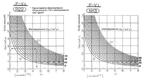
a) Determine Pd/Ps during operation based on the anticipated operating conditions of the system. Pd/Ps = Absolute value of discharge pressure = Discharge gauge pressure + 1.033 kgf/cm2 Absolute value of suction pressure Suction gauge pressure + 1.033 kgf/cm2
b) Find Vi from the compression ratio Vi = (Pd/Ps)1/k or Vik = Pd/Ps Vi can be found directly from the graph. (Working pressure is, however, absolute pressure)(Fig. 12)
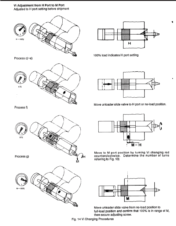
c) After determining the port, set the capacity control mechanism to the unload position.
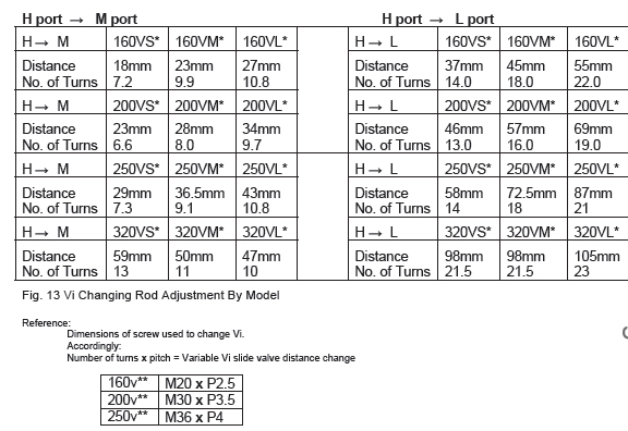
d) Determine the number of turns needed on the Vi changing rod for the particular compressor as given in Fig. 13.
e) Remove the cap seal on the Vi changing rod and loosen the lock nut. Turn the Vi changing rod clockwise (CW) and confirm that the variable Vi slide valve is at the maximum Vi position and that the Vi changing rod does not rotate (unreasonable force should be avoided when turning the Vi changing rod). (Adjusted to H port configuration before shipment). In case of medium port (M port), turn the Vi changing rod clockwise (CW) until it stops and set the variable Vi slide valve to the H port position.
f) Next, record the position of operation start (confirm the position of the stamp on the screw head). Turn the Vi changing rod counterclockwise the number of rotations indicated for the particular compressor as given in Fig. 13. After adjusting, secure the lock nut (approx. 1/12 of a turn after contact with the casing). When securing the lock nut, be sure that the Vi changing rod does not rotate out of position.
g) Set the capacity control mechanism to the full load position. If the needle pointer of the capacity control indicator indicates the specified porti range on the dial, proper adjustment is confirmed. An amplitude is provided between the M and H graduations on the indicator dial because the M and H positions shift depending on whether the compressor is a 160SML, 200 SML or 250 SML model as well as on the rotor length, of which there are nine. Since the graduations on the dial are common to all models, an amplitude is provided. When the Vi changing rod is adjusted the correct number of turns and the needle pointer position is within the specified range, adjustment can be considered correct.
h) Secure the hex head cap nut (453) for the Vi changing rod securely (rotate approx. 1/12 turn after contacting casing).
Precautions when changing Vi.
1. The Vi should be changed only when the compressor is stopped and the capacity control mechanism is set to the no-load position.
2. Unreasonable force should not be applied to the mechanism provided on L port and M port compressors.
3. If the Vi needs to be positioned midway between two different ports, select the best port referring to the capacity chart. Do not use variable Vi except for L, M and H ports.
4. The Vi should not be changed frequently in an attempt to adjust to small changes in the compression ratio, which may arise during normal operations. If no substantial change in operating conditions (e.g., a change in evaporative temperature) is required, the Vi should be changed only in the autumn and spring following the respective summer and winter seasons.
1.6 Other Component Mechanisms
a) The radial load of the compressor is absorbed by white meal-lined bearings while the axial thrust load on the rotors is absorbed by an angular contact ball bearing. The balance piston of the V-Series compressor M rotor is somewhat larger in diameter than that of a conventional screw compressor in order to allow for a decrease in the oil pressure load which is used for pressure difference lubrication.
b) A new, single balance type mechanical shaft seal is used on the drive shaft to protect the shaft from refrigerant leakage. The mechanical seal utilizes O-ring packing to allow service with various different refrigerants. A combination of carbon and metal is used to assure the durability of the frictional parts and
the sealing effect.
c) A cam is provided to indicate the position of the variable Vi slide valve and unloader slide valve. The capacity control ratio is shown on the dial indicator. Capacity control indication can be output to a remote indicator using the electric circuit provided.
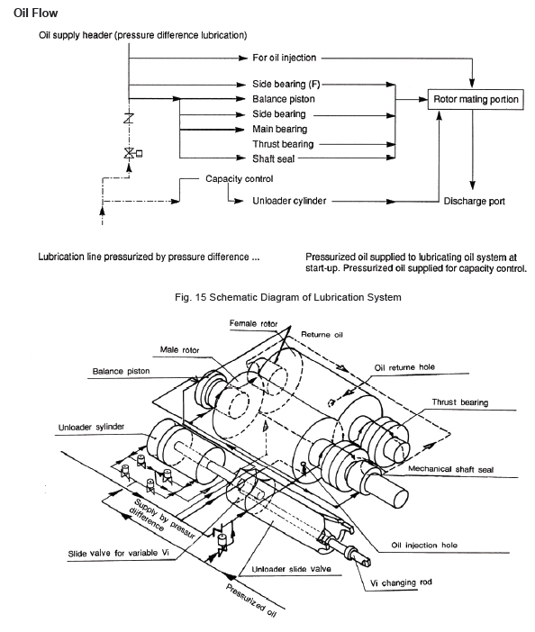
d) Compressor oil flow Oil for lubrication and for injection is supplied from a high pressure side oil tank by the pressure difference with the low pressure side or by an additional pump. Regarding oil injection, conventional compressors have oil injected into the triangular blow hole in the mating portion of the unloader slide valve but V-Series compressors utilize a system whereby oil is supplied from a fixed position on the M rotor side rotor casing.
e) Unlike with conventional screw compressors, oil is also supplied to the F rotor side bearing directly from the suction cover.
Oil Flow
2. Exploded View of V-Series Screw Compressor
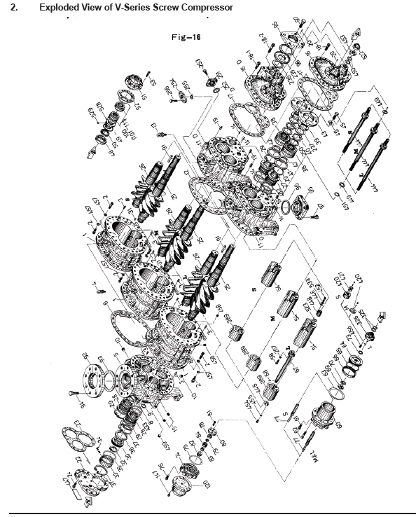
2.1 MyCom Parts List
No. Parts Name
1 Main Rotor Casing
2 Hexagon Socket Head Cap Screw
3 Alignment Pin
4 Hanger Bolt
5 Suction Cover
6 Gasket, Suction Cover
8 Spring Pin
9 "O"Ring
10-A Plug
10-B Plug
10-C Plug
10-D Plug
11 Bearing Head
12 Gasket, Bearing Head
13 Hanger Bolt
14 Spring Pin
16 Bearing Cover
17 Gasket, Bearing Cover
18-1 Hexagon Socket Head Cap Screw
18-2 Hexagon Socket Head Cap Screw
19 Alignment Pin
20 Spring Pin
21 Plug
22 Balance Piston Cover
23 Gasket, Balance Piston Cover
24 Hexagon Socket Head Cap Screw
25 Male Rotor
26 Female Rotor
27 Main Bearing
28 Side Bearing
29 Stop Ring
30 Balance Piston
31 Key, Balance Piston
32 Stop Ring
33 Sleeve, Balance Piston
34 Set Screw
35 "O"Ring
36 Spacer
37 Stop Ring
38 Thrust Bearing Assembly
No. Parts Name
39 Lock Nut
40 Lock Washer
41 Spacer, Thrust Bearing Outer Race
42 Spacer, Thrust Bearing Alignment
43 Thrust Bearing Gland
45 Hexagon Head Bolt
46 Lock Washer
48 Retainer, Oil Seal
49 "O"Ring
50 Oil Seal
51 Seal Cover
52 Gasket, Seal Cover
53 Hexagon Socket Head Cap Screw
54 Unloader Slide Valve
58 Hexagon Socket Head Cap Screw
60 Unloader Cylinder
61 Hexagon Socket Head Cap Screw
62 Hexagon Socket Head Cap Screw
63 "O"Ring
64 Unloader Piston
65 "O"Ring
66 Cap Seal
67 Push Rod, Unloader Slide Valve
68 Guide Pin
69 Lock Nut
70 Lock Washer
73 "O"Ring
74 Unloader Cover
75 "O"Ring
76 Hexagon Socket Head Cap Screw
77 Unloader Indicator Cam
78 Ball Bearing
81 Hexagon Socket Head Cap Screw
82 "V"Ring
83 Spring
84 Retainer
91 Shaft Key
100 Assembly, Mechanical Seal
120 Assembly, Unloader Indicator
137 Unloader Indicator
237 Torsional Slip Washer
No. Parts Name
250 Washer, Thrust Bearing
267 Spring Washer
289 Vi Slide Stop
325 "O"Ring
326 Gland, "O"Ring
420 Unloader Spacer
421 "O"Ring
432 "O"Ring
433 "O"Ring
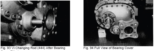
444 Vi Adjusting Rod
445 Washer
446 Vi Square Washer
447 Name Plate
448 Bushing
449 Thrust Washer
450 "O"Ring
451 "O"Ring
452 Hexagon Socket Head Cap Screw
453 Hexagon Nut
454 Hexagon Socket Head Cap Screw
455 Spring Washer
456 Hexagon Socket Head Cap Screw
457 Spring Washer
458 Plug
459 Plug
522 Domed Cap Nut
523 "O"Ring
528 Sleeve, Oil Seal
529 Set Screw
533 Spring Washer
605 Plug
No Parts Name
607 Plug
3. Disassembly of V-Series
3.1 Preparations for Disassembly
Disassembly work on a base-mounted compressor unit is limited to the shaft seal; thrust bearing, unloader cylinder and balance piston section. Disassembly and inspection work on other parts of the compressor should be done with the unit removed from the base and positioned for maximum access and ease of disassembly. Disassembly and inspection work as well as handling of compressor parts should only be undertaken after carefully reading the instructions given in this manual.
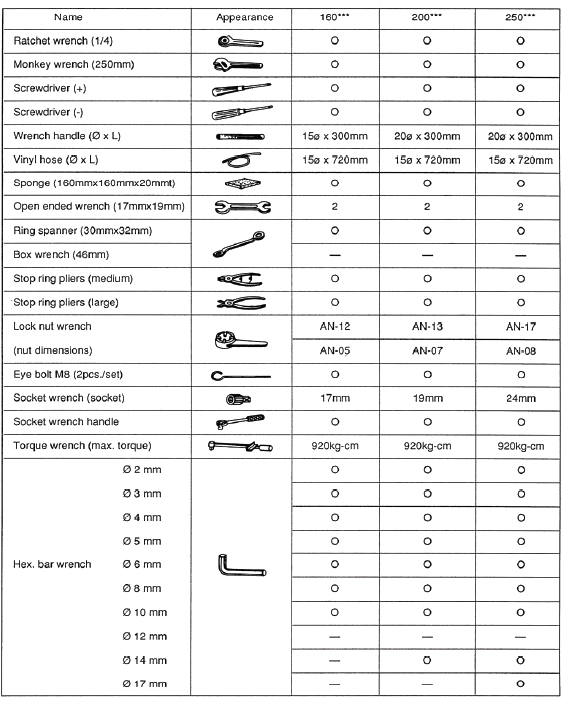
3.2 Hand Tool Kit (ref. last page)
Common hand tools such as a hammer, monkey wrench, file, scraper, sandpaper (fine grain) as well as the hand tool kit supplied with the compressor should be prepared prior to commencing disassembly work. In addition cleaning fluid, fresh lubricating oil, and waste cloth should be available. Work is best performed on a large surface plate positioned on a suitably large workbench. If a surface plate is unavailable, a steel plate having dimensions of at least 800 mm x 1,000 mm and supported on a low stand is a good substitute. Needless to say, work should be performed in a location that is well lit, dry and free from sand and dust.
3.3 Removing Compressor
3.3.1 Recovering Refrigerant
Refrigerant under high pressure is sealed up to the check valve of the screw compressor unit. Before the compressor is removed from the base, internal pressure should be reduced to atmospheric or slightly lower pressure. The methods for reducing pressure inside the compressor vary according to the type of compressor. In the case of a Freon refrigerant system, the following method should be used in order to prevent refrigerant gas from being discharged into the atmosphere.
a) Transfer the refrigerant to the low-pressure side of the system using a bypass valve.
b) If the system incorporates two or more compressors, draw out the refrigerant from one compressor to another (while operating the other compressor).
c) Recover the refrigerant using a small, portable compressor.
Whatever the method, the compressor should be disconnected with a slight positive pressure and the temperature the same or slightly higher than ambient air temperature. If it is disconnected with the inside under vacuum and the temperature lower than the ambient air temperature, air and moisture readily enter and may condense, leading to freezing at low temperature.
3.3.2 Disconnecting Auxiliary Equipment
Disconnect parts such as the drive coupling, suction/discharge piping, lubrication piping and other pipes such as those for liquid injection and the economizer as well as all control wiring and mounting bolts.
*When removing piping, a drain pan should be positioned under the joint being loosened to catch oil drips.
3.3.3 Raising and Removing Compressor
The weight of the suction piping bears on the suction port of the compressor. After removing the bolts securing the pipe to the port, suspend the suction piping and cover the suction port flange.
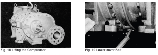
Lift the compressor and remove the 68 bolts (2) that secure the bearing head, suction cover and rotor casing before placing the compressor on the workbench. These bolts cannot be accessed once the compressor is sitting on the workbench. Since the compressor and its component parts are heavy, the disconnection and lifting work involves some danger. Take all necessary safety measures and arrange to support the compressor on matching steel stands or square timbers (100 mm x 100 mm).
3.4 Disassembly Sequence
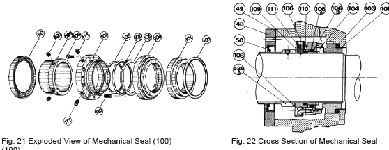
Disassembly and inspection of V-Series compressors should be carried out according to the following work sequence. For model D, the discharge flange portion extends from the leg of the compressor. Place a square timber or piece of lumber under the compressor or position so that the flange extends beyond the surface plate (see Fig. 20).
Disassembly Sequence
1) Mechanical shaft seal (100)
2) Unloader indicator (139)
3) Unloader cover (74)
4) Unloader piston (64) and cylinder (60)
5) Blind cover (22)
6) Balance piston (30)
7) Bearing cover (16) and Vi changing rod (444)
8) Thrust bearing (38)
9) Suction cover (5) and side bearing (28)
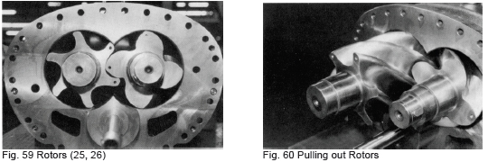
10) Rotors (25,26) and rotor casing (1)
11) Slide valve for variable Vi (289) and unloader slide valve (54)
12) Bearing head (11) and main bearing (27)
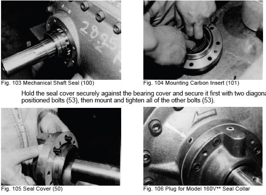
3.4.1 Mechanical Seal (100)
3.4.1.1 Disassembly
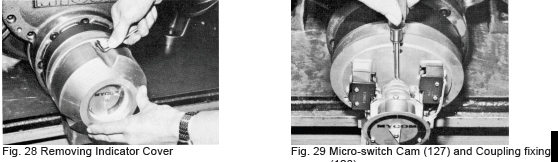
A new balance type single seal (100) is incorporated into V-Series compressors. A combination hard metal and carbon alloy is used for the frictional surface of the seal and an O-ring is provided for packing. As shown in Fig. 22, the balance type mechanical seal functions well under a wide range of conditions.
An oil seal (50) is fitted to the inside of the seal to act as an oil retainer. Because the frictional portion of the seal is subject to wear due to the rapid rotation of the shaft, a collar (109) is provided for the friction portion on models 200~250 so that the friction portion can be replaced.
Component parts of mechanical seal assembly
(48) Seal retainer (104) Seal ring (110) Spring
(49) O-ring (106A) O-ring (111) Set screw
(50) Oil seal (106B) O-ring (528) Sleeve, oil seal
(101) Carbon insert (108) Drive pin (529) Socket detent screw
(103) O-ring (109) Shaft seal collar
a) Remove four of the six hex-head socket cap screws (53) securing the seal cover (51), leaving two screws symmetrically positioned. Now loosen the remaining two screws alternately, allowing the shaft seal spring (110) to push off the cover slightly. If the cover adheres to the gasket, free it manually after the screws have been loosened.
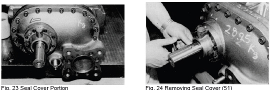
b) Remove the seal cover. The carbon insert (101) is fitted inside the cover. Draw the cover out over the end of the shaft being careful to prevent the carbon from hitting against the shaft. Next, remove the O-ring (49) between the seal cover (51) and the seal retainer (48).
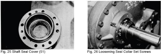
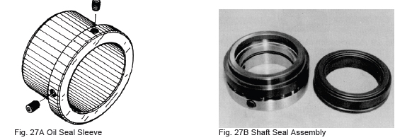
d) Loosen the setscrews (111) securing the shaft seal collar (109). In the case of Model 160, the plugs must first be removed from the bearing cover before a hex wrench can be inserted. In the case of model 200 and above, start from the seal cover disassembly procedure. Loosen the setscrews 34 turns (do not remove completely) until the end clears the shaft and enters the seal collar.
e) Grasp the seal collar (109) with your fingertips and withdraw carefully, making sure that the setscrew points do not catch on the shaft and scratch it.
f) Insert two eye bolts into the screw holes in the seal retainer (48) and draw it off parallel to the shaft. Be careful not to slant the retainer when withdrawing.
g) Remove the sleeve of the oil seal (528) after loosening the two setscrews (529).
3.4.1.2 Inspection
a) Inspect the frictional surfaces of the carbon and seal ring (104). A carbon with a smooth, unblemished face can be reused but if there are any signs of damage or peeling, replace the carbon, otherwise oil leakage may result.
b) Inspect the O-rings. With Freon refrigerant systems, the O-rings may suffer from swelling or deformation. If any abnormality is observed in an O-ring, replace it. A total of four O-rings are used for the seal cover, seal carbon and seal collar.
c) Inspect the frictional surface of the oil seal sleeve (528). If any wear is found, replace the oil seal and the sleeve with new parts. Since the oil seal is specially designed for the compressor, only genuine parts should be used.
d) If the seal cover gasket (527) proves difficult to remove when the seal is being disassembled, replace with a new one.
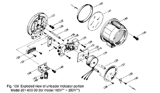
3.4.2 Unloader Indicator
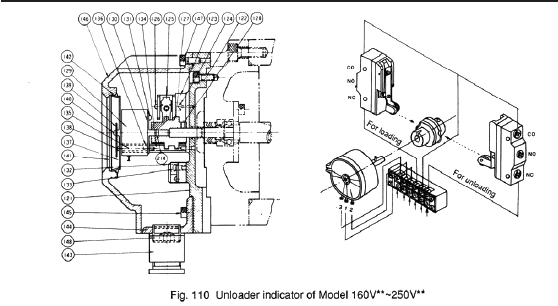
The unloader indicator shows the position of the unloader slide valve (54) based on conversion of the angle of rotation of the cylinder cam (77) to an electric signal. Two types of unloader indicator are available. One is a contact resistance potentiometer type and the other is a non-contact electronic type. Both are used for the same purpose as a rule. An explosion-proof indicator is also available as an option for special applications.
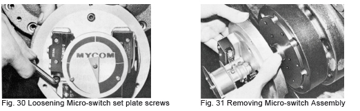
3.4.2.1 Removing Unloader Indicator Assembly
When disassembling the compressor, the unloader indicator should be removed as an assembly.
a) Detach the wiring to the unloader indicator and remove the three hex-head (147) securing the indicator cover (146)
b) The indicator cover, glass (141) and glass spacer (142) can now be removed. Be careful not to drop the glass or glass spacer.
c) The micro-switch cam (127) or coupling which connects the potentiometer or magnetic turntable and cylinder cam is located on the unloader cover side. Loosen the fixing screws (128) to free the cylinder cam.
d) Remove all of the hex socket head cap screws (122) securing the micro-switch base plate (121) to the unloader cover.
e) Draw out the unloader indicator parallel to the cylinder cam.
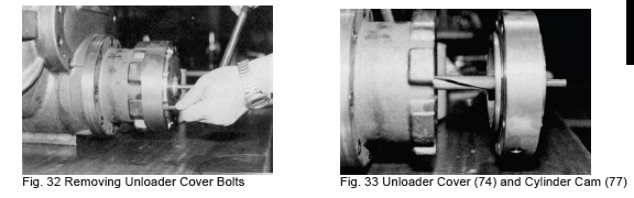
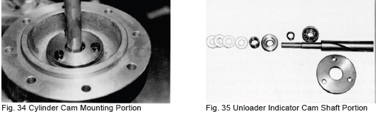
3.4.3 Unloader Cover (74)
The cylinder cam (77), shaft bearing (78) and seal are mounted in the unloader cover (74) provided at the end of the unloader cylinder (60). It is not necessary to disassemble these parts unless there is some abnormality (e.g., seal leakage or cylinder cam groove wear).
3.4.3.1 Disassembly
a) Remove the hex-head cap screws (76) securing the unloader cover (174) to the cylinder (60).
b) The cylinder cam (77) fixed to the cover is fitted in the bore of the unloader push rod (67) and the cam groove mates with the push rod pin. Pull of the cover parallel to the cylinder center.
3.4.3.2 Inspection
a) If the indicator is not actuating normally, check the cylinder cam groove, bearing and slotted pin (unloader push set side) for abnormality.
b) If there is refrigerant or oil leakage, replace the Teflon V-ring (82). In such a case, the shaft seal portion of the cylinder cam (77) should be disassembled
according to the following procedures.
1) A bearing gland (80) provided at the unloader cover cylinder side secures the cylinder cam (77). Remove the bearing gland (80) by loosening and removing the hex-head cap screws (81).
2) The cylinder cam (77), ball bearing (78) and stop ring (79) can now be removed together. If the cylinder cam and ball bearing are to be replaced, remove the stop ring first and replace the cylinder cam and ball bearing.
3) A spring retainer (84), spring (83) and Teflon V-ring assembly (82) are fitted inside the cover.
4) Check the packing and the groove in the cylinder cam for damage or abnormal wear and replace if necessary.
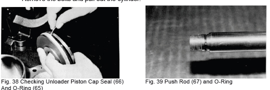
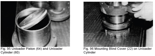
3.4.4 Unloader Piston (64) and Unloader Cylinder (60)
3.4.4.1 Disassembly
a) Pull out the unloader piston to the full load position. If the Vi is adjusted to the H port, the unloader piston will stop a bit closer than otherwise. Straighten the claws of the lock washer (70) on the lock nut (69) securing the piston (64) to the push rod (67).
b) Loosen the lock nut (69) using the lock nut wrench provided in the tool kit. If the wrench does not reach the nut, turn the Vi changing rod counterclockwise to shift the variable Vi slide valve (289) to the L port position and then pull the piston out further.
c) Pull out the unloader piston using two eyebolt screws secured in the two screw holes located in the unloader piston.
d) The unloader cylinder is fitted to the blind cover (22) by two short hex-head socket cap screws (61) and to the suction cover by six long hex-head socket cap screws (62). Remove the bolts and pull out the cylinder.
e) Alternately, the blind cover and cylinder can be removed together as an assembly from the suction cover by removing the six long hex-head socket cap screws (62) securing the cylinder to the suction cover and the blind cover fitting screws (24). In this case, the cylinder will not drop off even if the bolts are removed because the cylinder remains fixed to the suction cover. Draw out the cylinder from the suction cover and disassemble.
3.4.4.2 Inspection
a) Inspect the cap seal (66) and O-ring (65) on the unloader piston (64) and replace if any damage or abnormality is found. These parts should be replaced at least once every two years.
b) The inner surface of the cylinder may sometimes be coated with oil residue or scored. Finish the inner surface with fine emery paper after cleaning.
c) Inspect the push rod (67) and O-ring (65) on the unloader piston and the O-ring (63) on the cylinder. If the O-rings show signs of deformation, or have become hardened, replace with new ones.
3.4.5 Blind Cover (22)
Remove the bolts (24) that secure the blind cover (22) to the suction cover (5), leaving one bolt in place at the top to prevent the cover from falling suddenly.
The blind cover is fitted to a flat flange (92) on the suction cover and is held in place with the bolts only. When the gasket has come free, support the cover firmly and remove the last bolt. If the gasket adheres to the cover and flange, tap the side of the blind cover lightly with a hammer to separate the gasket.
3.4.6 Balance Piston (30) and Balance Piston Sleeve (33)
With screw compressors the male rotor is subjected to strong thrust load from the discharge side and rotates considerably faster than the female rotor. If the same type of thrust bearing were used for both the male and female rotors, the male side bearing life would be much shorter.
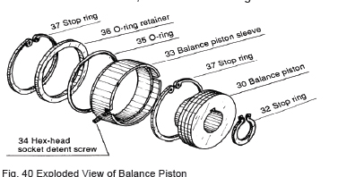
A piston (30) is provided on the end of the drive shaft of the male rotor to offset thrust load hydraulically. This piston is commonly called the balance piston.
The clearance between the balance piston and the sleeve is extremely small (smaller than the clearance between the bearing and the shaft) in order to prevent oil leakage.
3.4.6.1 Disassembly
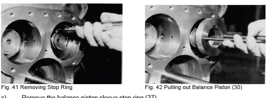
a) Remove the stop ring (32), which secures the balance piston (30) to the shaft using a pair of pliers. Screw an eyebolt into the hole in the balance piston and pull out parallel to the shaft. The balance piston key (31) will remain in the keyway. Leave the key as is.
b) Hex-head socket set screws (34) are screwed into both sides to prevent rotation of the balance piston sleeve (33). Loosen the F side screw and remove the M side screw or screw in until the head is recessed in the suction cover.
c) Remove the balance piston sleeve stop ring (37). Since the O-ring (35) pushes on the stop ring (37), it can easily be removed by pushing on the sleeve (33).
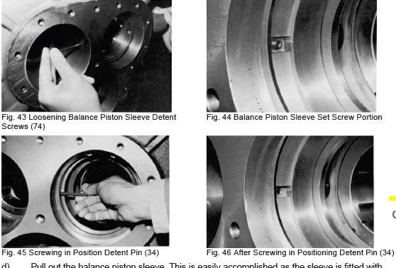
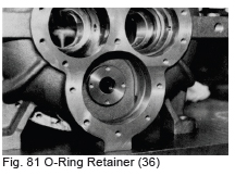
d) Pull out the balance piston sleeve. This is easily accomplished as the sleeve is fitted with some clearance Now remove the O-ring (35) and O-ring retainer (36).
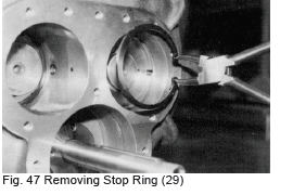
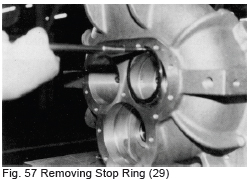
e) If you plan to remove the side bearing (28) also, at this time remove the inside stop ring (29).
3.4.6.2 Inspection
Since the clearance between the balance piston (30) and the balance piston sleeve (33) is smaller than the clearance between the rotor shaft and the bearing, the sleeve (33) may experience wear. If the sleeve dimensions exceed the service limits indicated at the end of this manual, replace the sleeve. The clearance provided on the periphery of the balance piston is designed to be adjusted by the peripheral clearance and elasticity of the O-ring but sleeve wear is not unusual. Inspect the O-ring (35) and replace if any deformation is found.
3.4.7 Bearing Cover (16)
The structure of this portion of the compressor differs between Model D and Model G units. Model D is provided with a discharge flange (95). For this reason the weight of Model D units is unbalanced, so particular care should be taken when working with it.
3.4.7.1 Disassembly
a) Remove all bearing cover fixing bolts (18-1, 18-2, 18-3) and insert one or two headless stud bolts into holes in the top of the cover.
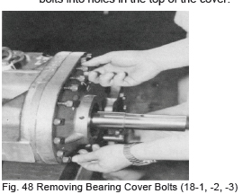
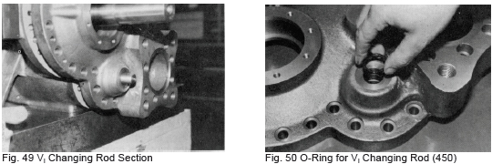
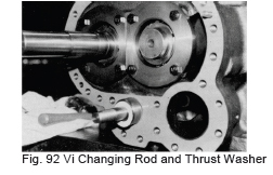
b) Remove the cap on the Vi changing rod (444) and remove the lock nuts (453).
c) Threaded blind holes are provided at symmetric points on the bearing cover (16) (on recently manufactured compressors these blind holes are closed with vinyl caps). Screw the bolts (18-1, -2, -3) in evenly to press off the bearing cover. When sufficient clearance is established, separate the gasket (17) from the flange face using a spatula. Take care not to damage the gasket when removing.
d) The cover will come free of the parallel pin as clearance is increased. On Models 200-250, a hanger bolt is provided on the top edge of the cover. Suspend the cover from a block before it comes fully free.
3.4.7.2 Inspection
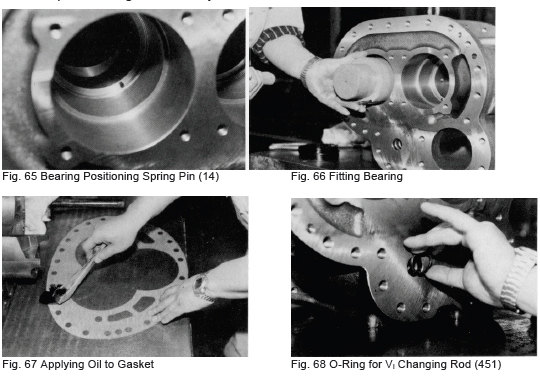
Inspect the parallel pin to be sure it is not bent. Also inspect the gasket, Vi changing rod O-rings (450, 451) and thrust washer (449) and replace if any abnormality is found.
3.4.8 Thrust Bearing (38)
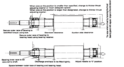
The thrust bearing is one of the most important components of the screw compressor. Maximum compressor performance depends on proper installation and adjustment of the thrust bearing otherwise operation problems may result. For this reason, maximum care should be taken when disassembling and reassembling the bearing. The thrust bearing used on V-Series compressors is an angular type face-to-face duplex bearing with special retainer of high accuracy. This bearing receives thrust load only as the outer race is clearance fitted. The bearing plays an important role in determining the clearance between the discharge end face of the rotor and the bearing head.
3.4.8.1 Disassembly
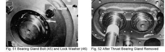
a) Straighten the lock washer (46) claws on the bolts (45) securing the thrust bearing washer (43) and remove the bolts. Support the bearing gland (41) by hand when removing the last bolt so that it does not fall down.
b) Straighten the claws on the lock washer (40) for the lock nut (39) that secures the inner race of the thrust bearing to the shaft then loosen and remove the nut. A thin steel lining plate (237) is provided between the lock nut (39) and the washer (40). Handle the lining plate carefully and store in a safe place. A thrust washer is also provided between the lock washer and the inner race.
c) The thrust bearing inner race and the shaft are clearance fitted. Insert a 1-2 mm wire with a flat bent point into the clearance between the outer race and the bearing step (41), hook the bearing step and remove the bearing.
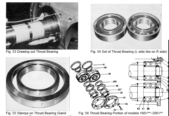
d) The thrust adjusting washer (42) and thrust bearing step (41) are provided behind the thrust bearing (some models do not have this arrangement for structural reasons). Parts are stamped to indicate those for the Male (M) rotor and those for the Female (F) rotor. Keep related parts together and do not mix. Improper assembly will cause dimensional errors and compressor seizure (refer to Fig. 55).
No. Name 160V**~200V** 250V**
38 Thrust Bearing 2 sets 2 sets
39 Lock Nut 2 pcs. 2 pcs.
40 Lock Washer 2 pcs. 2 pcs.
41 Thrust Bearing Step 2 pcs.
42 Thrust Bearing Adjusting Washer 2 pcs. 2 pcs.
43 Thrust Bearing Tightening Washer 2 pcs. 2 pcs.
45 Hex-Head Bolt 8 pcs. 8 pcs.
46 Hex-Head Bolt Lock Washer 8 pcs. 8 pcs.
237 Thrust Lining Plate 2 pcs. 2 pcs.
250 Thrust Bearing Washer 2 pcs. 2 pcs.
3.4.8.2 Inspection
a) Clean the thrust bearing thoroughly and blow dry. Inspect the ball bearings and races. The ball bearings should be shiny bright and the ball cages free of burrs. Also, check the clearance between the balls and cages for the bearing step (41).
b) Holding the inner race horizontally, spin the outer race rapidly. If any abnormal vibration is felt through your fingers, further careful inspection is needed. The vibration may be caused by fine dust particles or be a fault in the bearing.
c) Though the actual service life of a bearing depends on operating conditions, in principle the bearing should be replaced after 30,000 hours of operation. This period is shortened somewhat by oil fouling and by changes in temperature and load conditions, however. If any abnormality, even of the slightest nature, is found in a bearing, replace it with a new one.
3.4.9 Suction Cover (5) and Side Bearing (28)
3.4.9.1 Disassembly
a) Remove all bolts securing the suction cover (5) to the rotor casing (1). Remember that several of the lower bolts were removed when the compressor was lifted off the base and positioned on the workbench.
b) Screw several of the bolts into the threaded blind holes provided on the rotor casing side to press the suction cover off evenly. The bolts should be alternately tightened little by little in order to press the cover off evenly. When clearance between the cover and the casing flange is sufficient, separate the gasket (6) from one side.
c) After removing the parallel pin (3), the rotor shafts and the unloader push rod (67) remain connected to the suction cover (5). Slide the suction cover away from the rotor casing in line with the rotor shaft. Be sure to keep the rotors in the casing (there is a possibility that they may come free with the suction cover due to friction).
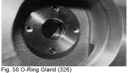
d) Remove the O-ring gland fixing screw (456) and remove the O-ring gland (326).
e) To remove the side bearing (28), first remove the stop ring (29), and then push the side bearing out from the rotor side. If a hammer must be used to free the bearing, cushion with a wooden block or the like to prevent damage.
3.4.9.2 Inspection
a) Inspect the unloader push rod (67), O-ring (73) and suction cover side O-ring (9) for deformation or other damage and replace with new ones if necessary.
b) Inspect the inner face of the side bearing (28) for foreign matter imbedded in the bearing metal. Also, measure the dimensions of the bearing (ref. Service limits provided at the end of this manual).
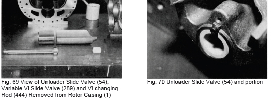
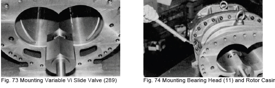
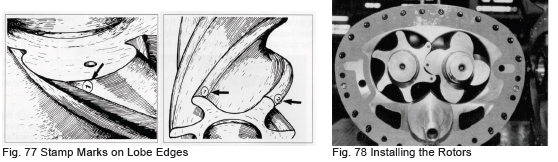
3.4.10 Rotors (25,26), Casing (1) and Variable Vi Slide Valve (289)
The variable Vi slide valve and the unloader slide valve are mounted together in the rotor casing.
3.4.10.1Disassembly
a) As the screw compressor rotors are very heavy, a hemp rope or nylon belt should be made available for use when the rotors are being removed. Suspend the rotor from the rope or belt as it is clears the casing. Either the male or the female rotor may be removed first. When removing the female rotor, rotate the rotor counterclockwise as you pull out. When the rotor is approx. two-thirds of the way out, lift it slightly and pull it all out the way, suspended from the
rope or belt.
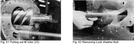
b) Remove the remaining rotor in the same manner, taking care not to damage the main bearing in the bearing head as you pull the rotor free.
c) Do not lay the rotors directly on the floor or the edges of the lobes may be damaged. Rest the rotor shaft ends on V-blocks.
d) Remove the hex-head socket cap screw (454) securing the lock washer (445) on the end of the Vi changing rod of the variable Vi slide valve (289) and remove the lock washer (445).
e) Turn the bearing side rod counterclockwise and draw the rod out. When the threaded portion comes free, pull it out of the bearing head. Place the thrust washers (449) together to prevent them from becoming lost.
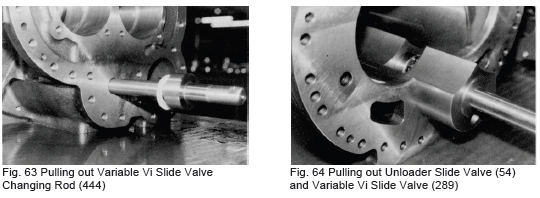
f) Pull the unloader slide valve (54) and the variable Vi slide valve (289) out of the casing while holding the unloader push rod. By pulling on the variable Vi slide valve changing rod (444), the unloader slide valve (54) can be separated.
3.4.10.2Inspection
a) Inspect the rotor journals for damage. The shaft seal and bearing mounting portions must be inspected.
b) Inspect the rotor lobes, especially the edges, for damage or abnormal wear. If the compressor has been operating normally, there should be no damage found. If, however, scoring or scratches, etc. are found, it points to a problem with the suction strainer as such damage can only be made by foreign matter entering the system.
c) Inspect the unloader slide valve (54) and the frictional surfaces and clearance between the variable Vi slide valve (289) and the casing (1). Also, check if the Vi changing rod (444) and the unloader slide valve bushing (448) are fitted together. If any wear or abnormal fitting is found, replace the parts.
d) Inspect the inner surface of the rotor casing. If no rotor damage is found, there should be no damage or abnormality of the casing inner surface either. If rotation traces are visible on the inner surface of the rotor casing, a problem with the journals is the most probable cause. Performance will remain unchanged despite wear of up to 0.3% of the rotor diameter; excessive wear of the leading edges of the rotors will result in a drop in performance.
e) With some special applications, the bearing journal and the shaft seal portions are finished with chrome plating. If any damage is found, contact the nearest MYCOM subsidiary for repair or replacement.
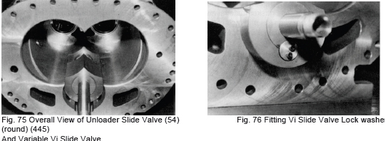
3.4.11 Bearing Head (11) and Main Bearing (27)
Normally, further disassembly of this portion of the compressor is not required as there is nothing to be gained from separation of the bearing head and rotor casing. Leave the two joined together. To draw out the main bearing, remove the stop ring (29) from the bearing cover side using a pair of pliers and push the main bearing out from the rotor casing side. If the bearing fit is tight, tap out using a hammer cushioned with a plastic or wooden block. Do not strike the bearing directly with the vhammer. Inspect the rotor shaft and the inner diameter of the bearing. Also, examine the inner diameter of the bearing and the outer diameter of the rotor shaft to determine if any foreign matter is imbedded in the bearing metal. Inspect the O-ring (451) of the Vi changing rod (444) for damage or other abnormality.
4. Reassembly
When disassembly, inspection and any necessary repair work are completed, the compressor must be correctly reassembled. Before commencing reassembly, confirm that all parts are available. Reassembly work is essentially carried out in the reverse order of disassembly. All tools and parts should be cleaned thoroughly before beginning reassembly and parts should be coated with compressor oil before being mounted.
4.1 Bearing (11) Head and Main Bearing (27)
a) The main bearing is clearance fitted in some cases while it is lightly press fitted in others. Arrange a simple jig (washer and bolt) to fit the main bearing.
A positioning spring pin (14) is provided on the bearing head. Align the pin with the notch in the main bearing (11). If the bearing must be tapped in, cushion with a plastic or wooden block. If the bearing gets out of position as it is being inserted, remove and carefully insert again. Be sure to fit the O-ring oil retainer (432) provided on the outer diameter.
b) Mount the stop ring (29) to secure the bearing.
c) Confirm that the O-ring (451) is properly fitted in the hole for the Vi changing rod.
d) Apply oil to both sides of the gasket before fitting it between the bearing head and rotor casing. Since the positions of the holes in the gasket are unsymmetrical, care should be taken to position the gasket correctly.
4.2 Rotor Casing (1), Unloader Slide Valve (54), Variable Vi Slide Valve (289) and Bearing Head (11)
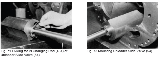
a) Unloader slide valve (54) Confirm that the Vi changing rod (444) moves properly. Mount the unloader push rod (67) and fit the gasket to the hole for the Vi changing rod shaft.
b) Rotor casing (1) Clean the oil injection holes thoroughly, fit the plug (10) and mount the unloader slide valve (54). Confirm smooth movement of the unloader slide valve.
c) If the rotor casing (1) and bearing head (11) have been separated, assemble them now (normally, these two parts are not disassembled). Tighten the bolts (2) to the specified torque in a symmetrical crisscross pattern. A number of the bolts on the bottom cannot be accessed at this time and must be tightened later when the compressor is raised.
d) Mount the Vi changing rod (444) from the bearing head side. Be careful not to forget to install the thrust washer (449). Push the unloader slide valve (54) to the discharge side and fit the female screw of the variable Vi slide valve on the Vi changing rod. When the end of the Vi changing rod extends from the Vi slide valve, secure the lock washer.
e) If the gasket on the bearing head protrudes into the rotor casing, trim the excess gasket material away. If the gasket is caught between the end face of the rotor and the bearing head, thrust clearance cannot be adjusted properly.
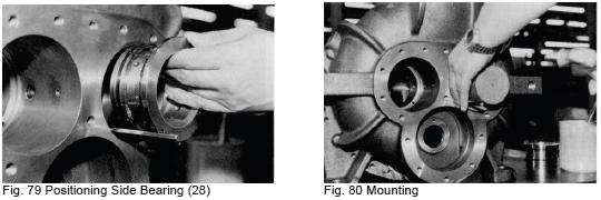
4.3 Rotor Casing (1) and Rotors (25,26)
a) Coat the main bearing and the shaft portion of the male rotor with compressor oil and install first. Suspend the rotor from a rope or strap at its mid point and insert into the casing half way. Release the rope or strap and push the rotor in fully.
b) The suction side leading edges of the female rotor stamped with the numbers “1” and “2” should be oriented toward the male rotor side.
c) Lift the male rotor with the rope or strap. The number “1” stamped on the leading edge of one lobe should be oriented toward the female rotor side.
d) Mate the rotors so that the leading edge of the male rotor lobe stamped with the number “1” fits between the leading edges of the female rotor lobes stamped “1” and “2” and push the female rotor in to half its length. Remove the belt suspending the female rotor and push it the remainder of the way in. Proper orientation of the male and female rotor lobes is essential, otherwise irregular lobe meshing will occur and the compressor will generate abnormal noise.
4.4. Suction Cover (5)
a) Fit the side bearing into the casing in the same manner as for the main bearing. An O-ring (433) for the oil retainer is provided on the outer diameter. Be sure to install the Oring (433). If the cover must be tapped in, cushion with a plastic or wooden block and tap around the positioning pin (8).
b) Secure the stop ring.
c) Mount the O-ring retainer (326) for the unloader push rod. The suction cover side also requires an O-ring so do not forget to mount during the assembly work.
d) Mount the balance piston sleeve in the order of stop ring (32), O-ring retainer (36), O-ring (35), balance piston sleeve (33) and stop ring (32). When installing the stop ring, tap the side face slightly to ensure that it fits snugly in the groove.
e) Secure the balance piston sleeve (33) with the hex-head socket detent set screw (34) from the female rotor side.
f) Turn the Vi changing rod (444) in the rotor casing/bearing head assembly in the counterclockwise direction to set the Vi to the L port position. Set the unloader slide valve (54) at the full load position.
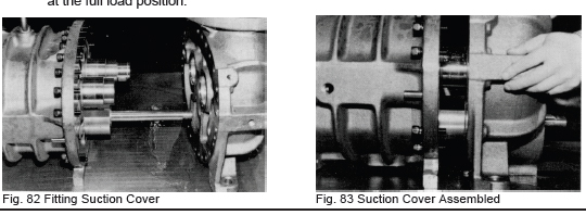
g) Slide the suction cover across the surface plate and align the suction cover O-ring retainer with the push rod (67)
h) Mate the side bearing (28) and rotor shafts and push the cover and casing together parallel with the shaft.
i) Drive the positioning parallel pin (19) in from the rotor casing side and secure the bolts (94).
j) Confirm that the unloader slide valve (54) and variable Vi slide valve (289) move normally. Rotate the male rotor shaft to confirm smooth movement.
4.5 Thrust Bearing (38)
a) Confirm the M and F stamps on the thrust adjusting washers (42) and mount the thrust bearings in the casing in the same direction as before disassembly.
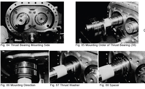
b) Care should be taken to exclude any foreign matter or dust particles from the space between the thrust bearing gland (41) and the adjusting washer (42).
c) The thrust bearing should be installed with the point of the “V” mark inscribed on the bearing pointed in toward the rotor side (refer to Fig. 86). If the thrust bearing is inserted with the “V” pointing in the opposite direction, end clearance will differ from that before disassembly because of the different sizes of the outer and inner race side surfaces.
d) Be sure that the mounting order is correct. If the lock washer claw is bent at the same point as before, the claw may break. For this reason it is best to replace the lock washer (40) with a new one. If new washers are not available, exchange the washers of the male and female rotors.
e) Fix the inner race of the thrust bearing to the rotor using the lock nut.
f) If the thrust bearing is being replaced with a new one, confirm that the end clearance of the bearing is secured while loosening the bolt little by little. Since the difference in the side faces of the inner and outer bearing races vary even if the bearing is within specifications, no clearance is secured in some cases. If the nuts are tightly fastened from the beginning, in this case the bearing balls will be pressed against the rolling contact surface and damaged. If no clearance is secured, grind the thrust bearing gland (41) or replace the thrust adjusting washer (42) with one or greater thickness. If only a slight clearance is required, a thing plate may be affixed to the thrust adjusting washer.
g) Press the rotor against the discharge end face with the inner race fixed to the rotor shaft.
h) The dial indicator mounted on the suction side rotor end must be set to the 0 position.
i) Fasten the thrust bearing-tightening washer (43) with the hex-head socket cap screw (45) and hex-head bolt lock washer (46) and torque to the value given in the table below.
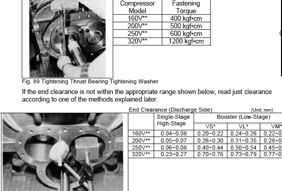
j) End clearance adjustment method when measured value is not within specifications.
1) When end clearance is larger than the specified value. This means that the distance of the rotor end face from the discharge end of the bearing head is too large when the thrust bearing is secured with the gland. Various methods for reducing the distance are available.
i. First method:
Since the dimension at “A” shown in Fig. 90B is too large because the thrust adjusting washer is too thick, the face of the washer must be ground down by the amount of the difference between the measured value and the specified value. To accomplish this, a high precision surface grind must be used to ensure that both sides of the washer are parallel. After machining, measure the thickness around the entire circumference of the washer using a micrometer. This method can be used for all models.
ii. Second Method
Insert a shim of the required thickness between the bearing gland (41) and the outer race of the bearing. The thickness of the shim is determined by the difference between the measured value and the specified value. A shim of brass or copper should not be used if the system refrigerant is ammonia because
these materials are easily corroded by the gas. An iron shim should be used instead.
2) When the end clearance is smaller than the specified value.
In this case, the rotor will not rotate when the lock nuts are tightened. The reason is that the thrust adjusting washer (42) is not thick enough or the bearing gland (41) is too thick. Accordingly, a shim of the required thickness must be inserted between the thrust adjusting washer and the inner race of the thrust bearing. Using a new thrust adjusting washer with the correct thickness is much better than adjusting the thickness with shims. If the gland is too thick, it should be ground to the necessary dimensions (since no gland is proved on the 250V** and larger compressor models, adjustment must be accomplished with the adjusting washer (42)). After adjusting the clearance, measure several times and confirm that the proper end clearance is achieved.
k) Rotate the male rotor manually to confirm smooth rotation.
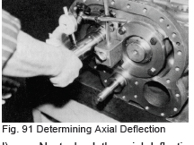
l) Next, check the axial deflection of shaft rotation with the dial indicator positioned on the oil seal fitting portion. Maximum deflection of the 0.015 mm is acceptable. Deflection may be cause by no uniformity of the thrust adjusting washer or mismatching of the stamped bearing parts. Even if the end clearance is within the specified value, disassembly and adjustment by changing the relative positions of the gland, thrust adjusting washer and bearing will be necessary. Accurate assembly of the bearing parts is vital for the long life and maximum performance of the compressor. If dust is caught between the parts, the deflection value will increase.
m) After completing end clearance adjustment, tighten the thrust bearing securely.
Notes:
1) Always use new lock nuts (39) and lock washers (40).
2) Be sure to position the shim between the lock nut (39) and the lock washer (40).
3) Tighten the lock nuts securely. Specified torque values are shown in the table in paragraph i)-(1) above. At the plant site, however, it may be necessary to use a hammer to tighten the nuts if a torque meter is not available. Take the utmost care to ensure that neither the lock nut nor lock washers are damaged.
4) When tightening the lock nut, mesh the lock nut and the claw of the lock washer and tighten the nut carefully to the specified torque value. Do not turn the nut counter-clockwise. After the necessary tightening torque is confirmed, bend the claw of the lock washer. The corners of the thrust bearing hexhead bolt lock washer (46) should also be bent back to lock.
4.6 Bearing Cover (16)
a) Fit the thrust washer (446) on the Vi changing rod (444).
b) Screw a long stud bolt into the bearing head and fit the gasket and the bearing cover, taking care not to damage the shaft seal portion. First mount the Vi changing rod (444), then align the parallel pin (3) and push the bearing cover onto the bearing head, being careful to maintain even alignment. Screw two bolts in at diagonal positions to assure the bearing cover is parallel. Secure the remaining bolts after the full face of the bearing cover contacts the bearing head.
4.7 Blind Cover (22), Unloader Cylinder (60) and Unloader Piston (64)
a) Fit the O-ring (65) on the unloader piston (64) and cover the cap seal (66). Mount the piston in the unloader cylinder (60) from the beveled (rotor) side.
Adjust the position so that the threaded blind hole for the piston faces the unloader cover side.
b) Fit the O-ring (63) between the unloader cylinder (60) and the blind cover (22) and mount the blind cover on the cylinder, securing it with two short bolts. (61).
c) Fit the gasket (23) and push the unloader cylinder (60) into the suction cover (5). Fit the blind cover (22) temporarily using two or three bolts. Fix the unloader piston (64) to the unloader push rod (67) using the lock washer (70) and lock nut (69). Be sure to bend the claw of the lock washer.
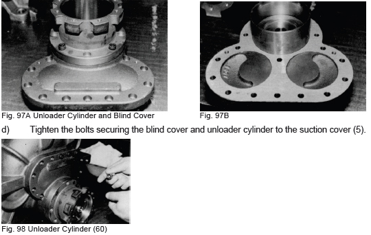
d) Tighten the bolts securing the blind cover and unloader cylinder to the suction cover (5).
e) Screw and eye bolt into the unloader piston (64) and manipulate to confirm smooth movement of the slide valve (54).
4.8 Unloader Cover (74)
When the shaft seal portion of the indicator cylinder cam (77) has been disassembled, assembly work is carried out according to Fig.100.
a) Fit the ball bearing (78) on the cylinder cam shaft. When pushing the bearing onto the shaft, apply pressure on the inner race of the bearing only, otherwise the bearing may be damaged. Push the bearing onto the stepped portion of the cylinder cam and fix with the stop ring (79).
b) Apply a generous coating of oil to the V-ring (82) and fit the V-ring on the cover side, positioning the top of the “V” of the ring to face the inside and the bottom of the “V” to face the outside.
c) Fit the spring (83) and the spring retainer (84) and mount the shaft of the cylinder cam assembled in a) above on the V-ring (82). Fasten the bearing (78) with the bearing gland (80).
74 Unloader cover
80 Bearing gland, cylinder cam
75 O-ring, unloader cover / unloader cylinder
81 Hex-head socket cap screw, bearing gland
76 Hex-head socket cap screw, unloader cover
82 Teflon V-ring, cylinder cam
77 Cylinder cam, unloader indicator
83 Spring, cylinder cam
78 Ball bearing, cylinder cam
84 Spring retainer, cylinder cam
79 Stop ring, cylinder cam ball bearing
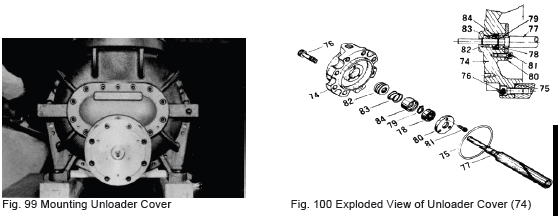
d) Rotate the cylinder cam (77) manually to confirm smooth rotation. Fit the O-ring (75) on the unloader cover (74).
e) Position the unloader slide valve (54) in the no-load position (piston at the innermost point) and push in the cover while mating the groove on the cylinder cam with the pin on the push rod (67). Fasten the screws (76) with the outlet of the unloader piston hydraulic piping facing up (ref. Fig.100).
4.9 Mechanical Shaft Seal
a) Clean the contact surface of the shaft seal thoroughly before assembling.
b) Carefully inspect the seal contact surface on the stepped portion of the shaft for flaws and scratches before assembling.
c) When mounting the seal retainer (48), confirm that it is positioned in the correct direction. Position the seal retainer so that the oil induction hole is located above the shaft. Be sure that the seal retainer detent screw (529) and the notch in the retainer are correctly mated and turn the seal retainer to the left and right using an eye bolt to confirm that it is securely fixed.
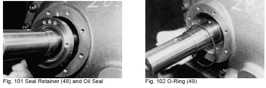
d) Next, insert the seal cover O-ring (49). Note that this part is sometimes forgotten during assembly.
e) Fit the oil seal sleeve (528) and secure the two set screws (529).
f) Mount the shaft seal assembly (100). Push the O-ring (49) in carefully so that it is not damaged. Two screws are provided for the seal collar (109). Secure the screws (111) making sure that they mate with the countersunk holes in the shaft. After mounting, push on the seal ring (104) manually to confirm axial
movement.
g) Fit the O-ring (103) for the carbon and the carbon insert (101) in the seal cover (50). Fit the gasket (52) on the seal cover (50) and position it correctly to match the oil holes in the bearing cover and then fit the seal cover by sliding it onto the shaft. When fastening the seal cover, the carbon should first contact the seal ring (104).
h) Model 160V has holes for the seal collar set screws in the bearing cover. These holes must be plugged with blind plugs after mounting the seal cover (ref. Fig. 106).
5. Disassembly and Adjustment of Unloader Indicator
The potentiometer (129), micro-switch (125) and micro-switch cam (127) are mounted in the automatic control indicator portion of the compressor.
5.1 Disassembly and Adjustment of Unloader Indicator (120)
a) Remove the machine screw (140) securing the indicator pointer (139).
b) Remove the machine screw (138) securing the dial plate (137).
c) The potentiometer mounting plate (130) is fitted between the dial plate support (1) (134) and dial support (2) (135). Loosen and remove support (2) by turning counterclockwise while holding support (1) securely.
d) When the right and left supports are removed, the potentiometer (129) can be removed together with the mounting plate (130).
e) The potentiometer is secured to the mounting plate with three machine screws (131).
f) The micro-switch (125) is secured with two long machine screws (126). Loosen these screws to remove the micro-switch. The micro-switch component on the right side is for the no-load position signal and the one on the left side is for the full-load position signal. The micro-switch set plate (123), secured by other screws (124), is mounted under the left side micro-switch component. The micro-switch component on the right side is for the no-load position signal while the one on the left side is for the full-load position signal. The micro-switch set plate (123), secured by other screws (124) is mounted under the left side micro-switch component. Adjustment of the micro-switch is accomplished using with microswitch cam (127).
g) The terminal block (132) and other parts can be removed by removing the screws (133) securing them.
5.2 Inspection
a) Only actuation of the electrical components needs to be inspected. Since a full rotation type potentiometer is used, test to confirm smooth resistance throughout the full rotation of the device. Operation in an atmosphere containing moisture or corrosive gas will lead to rusting of the components and resistance may change, resulting in faulty operation indication.
b) Check the actuation of the contact points of the micro-switch components using a tester (for details contact the Electric Department of Mycom).
5.3 Assembly and Adjustment
The procedures for reassembling the unloader indicator are the reverse of disassembly. Adjustment after assembly is, of course, very important. There are basically two aspects of adjustment.
1) The physical relationship between the micro-switch cam (127) and the slide valve (54).
2) The relationship between the no-load position and the resistance value of the potentiometer.
Adjustment of these factors should be carried out after the micro-switch base plate (121) has been mounted on the unloader cover (74).
a) The unloader cover is fitted on the compressor with the unloader piston (64) in the no-load position. Secure the micro-switch cam with the hex-head socket head set screw (128) to bring it into line with the countersunk hole in the unloader indicator cylinder cam (77). The microswitch cam (127) is then in the no-load position. Align the concave point of the micro-switch cam (127) facing the unloader cover (47) with the actuation arm point of the micro-switch (ref. “A” and “B” in Fig. 110).
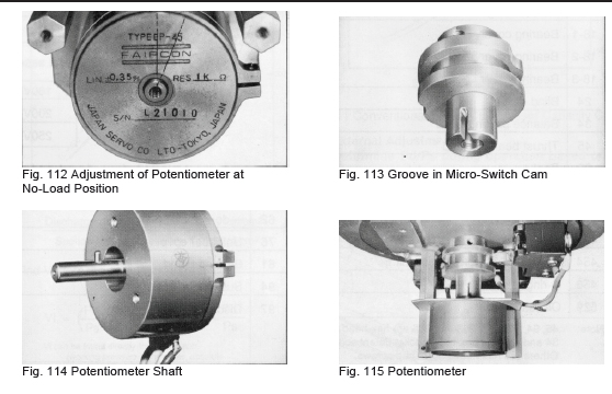
b) When mounting the potentiometer (129), fit the spring pin (214) of the potentiometer shaft in the groove of the shaft support (2) (135) (ref. Figs. 113,114).
c) Correct positioning of the potentiometer is established by the work indicated in the above paragraph b).
d) Fit the dial plate and mount the indicator pointer (139), aligning it to the no-load position. If a full load micro-switch is provided, adjust the micro-switch setting screw (126) so that it is actuated by the cam. Actuation of the micro-switch (125) is confirmed by moving the unloader slide valve (54) to the
full load position with oil pressure when the hydraulic pump can be operated or by supplying low-pressure air to the unloader piston (64). If the machine screws (126) of the micro-switch are loose, the micro-switch may slip out of position, resulting in irregular or faulty actuation. Secure the micro-switch tightly after confirming actuation.
e) After confirming proper actuation, connect the control wiring as before and mount the unloader indicator cover (146). Be careful not to pinch the wires with the cover. Disassembly, inspection and reassembly of the V-Series compressor unit are now completed.
6. Standards of Components
Compressor Oil
The quality of lubricating oil significantly affects the performance and life of the compressor. Important requirements of refrigeration system lubricating oil include suitable viscosity over a wide temperature range, low fluidity and high flash point. Taking the above-mentioned characteristics of lubricating oil into consideration, oil used should satisfy the following requirements:
1) Proper viscosity should be maintained within the potential working temperature range.
2) Low fluidity should be maintained at low temperature.
3) The oil should be chemically stable, with no corrosion effect on metal and no effects on system parts made of rubber.
4) The oil should not experience wax separation at low temperature.
5) The oil should not generate sludge or carbon under high temperature conditions.
6) The oil should be free from moisture and foreign matter.
7) The oil should be able to provide the necessary lubricating effect for a long period of time. Selection of Compressor Oil
a) First, consider the lubrication requirements of the compressor. Obviously, oil of proper viscosity must be supplied to the moving parts at all times.
b) Next, consider oil circulation throughout the system. Contradictory factors such as high oil viscosity in the evaporator and low oil viscosity in the compressor must be reconciled.
c) When using Halocarbon refrigerant, even though the proper initial viscosity was secured, a considerable change in viscosity is inevitable because under certain operating conditions the refrigerant will dissolve in the oil. For this ISO-VG46 (JIS K2211) grade oil is recommended.
Changing Compressor Oil Brands
When changing from a brand of oil normally used to a new brand, unexpected problems may be encountered due to incompatibility of the old and new oils when they are mixed. Exercise care when changing oil brands.
a) If the new oil is produced by a different manufacturer, consult with both makers to determine if the change will cause any problem.
b) Changing the viscosity grade of the same maker’s oil is acceptable, e.g., SUNISO 4GS Æ SUNISO 5GS.